HD44780 LCD Module driver for Windows 10 IoT

This is my first post about Windows 10 IoT and small computers (embedded) after some experiences in the past with the .Net MicroFramework (Netduino, in essence).

I must say that this Windows 10 is finally a small masterpiece, or “everything you ever asked and none never responded you”. The programming way is easy but very flexible, although still many bricks are missing (in development).

The source code on GitHub

Here is a very simple experiment, a bit vintage, of driving a common alphanumeric LCD module (HD44780-based) with a Raspberry PI 2 and Windows 10 IoT.

WP_001158

The project isn’t anything new, but rather kinda “refresh” of another of mine where the Netduino board was used (see below). Someone of you may wonder “why” still using a so-old LCD module when several graphics are available on the market. Well, my first answer is: “why not?”. As said, this project hasn’t any specific purpose (although many of you may dig into their “miracles box” and pull out an “almost useless” LCD module). The aim is to test how hard is to drive something well known.


Some credits…

I can’t miss to mention Laurent Ellerbach, who gave me some inspiration (and motivation) on pursuing those hacking/funny activities.


The hardware.

All you need is very easy to find:

  • Raspberry PI2 (with Windows 10 IoT installed)
  • any suitable HD44780 LCD display module (mine is a 4×20)
  • 74HC595 shift-register
  • 220 Ohms resistor (only if you need the backlight)
  • 10k Ohms trimpot (22k or 47k are fine the same)

For sake of simplicity, I won’t detail how to set up the Raspberry, but there are many articles which describe very well that. I followed the Microsoft site and everything went fine, except for the suggested SD minimum size: I found that a 8GB won’t work. Simply consider a 16GB.

RPI2-HD44780_schem

RPI2-HD44780_bb


The software.

I wanted to publish the project keeping the sources simpler as possible. A similar application won’t have sense in a complex hardware (full-featured TFT displays and HDMI monitors perform way better than this module). The general guideline is: if you find convenient to connect a LCD module to a RPI, then make it working in minutes.

Since the LCD module’s capabilities are very limited, I embraced the idea to expose the APIs as it were a kind of “Console”. Just a “write” and something more, where a background task should manage the physical transfer by itself.

The project contains two different demo:

  1. a basic one, where some strings’ content is reflected on the display;
  2. a slightly more complex demo, which gets a bunch of RSS news from the BBC.uk channel, and rotates the titles on the screen.


Basic demo.

    class BasicDemo
    {

        public async Task RunAsync()
        {
            //write a static string
            DriverHD44780.Instance.DrawString(
                "This is a basic demo",
                new Point(0, 0)
                );

            int n = 0;
            while (true)
            {
                //display a simple counter
                DriverHD44780.Instance.DrawString(
                    $"Counting...{n}",
                    new Point(0, 1)
                    );

                //display current time and date
                var now = DateTime.Now;
                DriverHD44780.Instance.DrawString(
                    now.ToString("T") + "   ",
                    new Point(0, 2)
                    );

                DriverHD44780.Instance.DrawString(
                    now.ToString("M") + "   ",
                    new Point(0, 3)
                    );

                n++;
                await Task.Delay(1000);
            }
        }

    }

WP_001159


RSS demo.

    class RssDemo
    {

        public async Task RunAsync()
        {
            //write a static string
            DriverHD44780.Instance.DrawString(
                "Getting RSS...",
                new Point(0, 0)
                );

            //get the latest news using a normal HTTP GET request
            var http = new HttpClient();
            var endpoint = new Uri("http://feeds.bbci.co.uk/news/rss.xml");

            var srss = await http.GetStringAsync(endpoint);
            var xrss = XDocument.Parse(srss);

            //extract the news items, and sort them by date-time descending
            var xnews = xrss.Root
                .Element("channel")
                .Elements("item")
                .OrderByDescending(_ => (DateTime)_.Element("pubDate"))
                .ToList();

            int n = 0;
            while (true)
            {
                /**
                * Loop the news as one per page
                **/

                //the first row is for the publication date-time
                var dt = (DateTime)xnews[n].Element("pubDate");
                DriverHD44780.Instance.DrawString(
                    dt.ToString("g"),
                    new Point(0, 0)
                    );

                //the three other rows are for the title
                var title = (string)xnews[n].Element("title");
                title = title + new string(' ', 60);

                for (int row = 0; row < 3; row++)
                {
                    DriverHD44780.Instance.DrawString(
                        title.Substring(row * 20, 20),
                        new Point(0, row + 1)
                        );
                }

                //wait some seconds before flipping page
                n = (n + 1) % xnews.Count;
                await Task.Delay(3000);
            }
        }

    }

WP_001165


Performance.

You may wonder how well performs the driver. Well, there are two stages involved in the displaying process:

  1. the calls from the main application to the driver;
  2. the physical data transfer.

Any invokation by the main app involves always the cache: no matter how many calls are made, because everything is hosted in memory. For this reason, any manipulation is irrelevant in terms of performance impact. However, a fixed rate (typically 200ms) there’s a cache dump to the LCD screen, that is: the physical data transfer though the SPI.

How long takes the entire screen dump via SPI?

The circuit is very simple, thus there’s no way to take the transfer faster than the machine execution speed. Even adjusting the SPI clock rate, the resulting duration won’t change notably. Please, bear in mind that a too high SPI clock rate could face signal degradation due the wire length. I used a perfect 1 MHz value, and you can see from the below screenshot that the total transfer duration is less than 30ms.

UNIT0000

If you are interested in a faster way to dump the data via SPI, I suggest to read the following section which requires a decent knowledge about electronics.


The old “LCD Boost” library.

The original project was tailored for the .Net MicroFramework (Netduino) and many things were optimized for speed reasons. Moreover, the NetMF had some leaky problems mostly due to the super squeezed CLR, thus many solutions were solved as it were a low-level device.

Here are some links to the original articles of mine:

Very fast SPI-to-parallel interface for Netduino

LcdBoost library for Netduino

The GDI library for Netduino targets a LCD module.

A playable Invaders-like game with a Netduino Plus 2.


Azure Veneziano – Part 2

This is the second part of my Internet-of-Things telemetry project based on Azure.

The source of the project is hosted in the azure-veneziano GitHub repository.

Here are the other parts:

In this article I’ll show you how to setup some components of Windows Azure, in order to make the system working.

I won’t cover details such as “how to subscribe to the Azure platform” or similar. Please, consider the several posts around the web, that describes very well how to walk the first steps, as well the benefits coming from the subscription.
A good place to start is here.

The system structure more in depth.

In the previous article there is almost no description about the system structure, mainly because the post is focused on the device. However, since here the key-role is for Azure, it’s better to dig a bit in depth around what’s the target.

structure

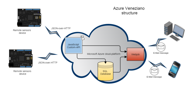
On the left there are a couple of Netduinoes as symbol of a generic, small device which interfaces with sensors, collects some data, then sends them to the Azure platform. This section is covered in the first part of the series.
The JSON-over-HTTP data sent by any device are managed by a “custom API” script within the Azure’s “Mobile Services” section. Basically a Node.JS JavaScript function which is called on every device’s HTTP request.
This script has two major tasks to do:

  1. parse the incoming JSON data, then store them into a SQL database;
  2. “wake-up” the webjob, because new data should be processed.

The database is a normal Azure SQL instance, where only two simple tables are necessary for this project. One is for holding the current variables state, that is every single datum instance incoming from any device. The other table depicts the “history” of the incoming data, that is the evolution of the state. This is very useful for analysis.

Finally, there is the “webjob”.
A webjob could be seen as a service or, more likely, as a console application. You can put (almost) anything into this .Net app, then it can started anytime. What I need is something like a endlessly running app, but in a “free-context” this service is shut-down after 20-30 minutes. That’s the way I used a trick to “wake it up” using kinda trigger from the script. Whenever new data are incoming the app is started, but can stay stopped whenever nothing happens.
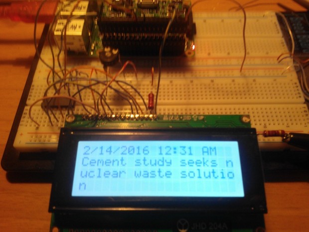
The webjob task is just sending a mail upon a certain condition is met. In this article I won’t show anything sophisticated, than a very short plain-text mail. The primary goal here is setting up the Azure platform, and testing the infrastructure: in the next articles we’ll add several pieces in order to make this project very nice.

Looks nice, but…how much does cost all that?

Just two words about the cost of the Azure platform.
Entering into the Azure portal is much like as walking in Venezia: full of intriguing corners, each one different from others, and always full of surprises. The platform is really huge, but surprisingly simple to use.

billing

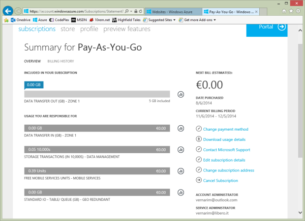
I say that I was surprised, because you’ll be also surprised by realizing that many stuffs come for FREE. Unless you want to scale up (and get more professional) this project, your bill will stick to ZERO.

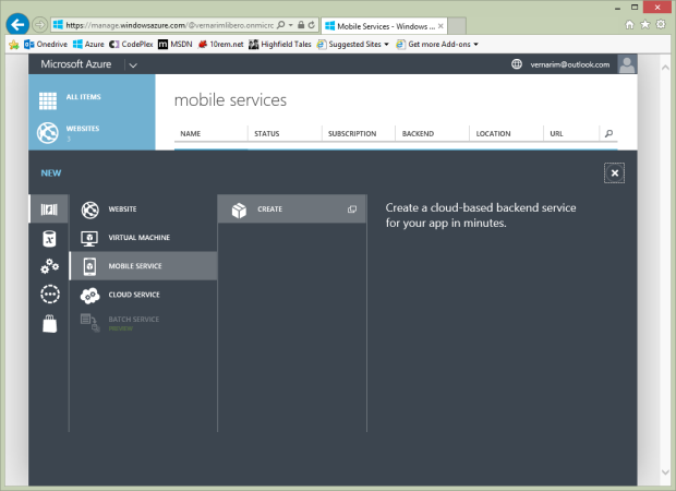
Setup the mobile service.

The Mobile Services are the most important components in order to interface any mobile device. The “mobile” term is rather oriented to devices like phones or small boards, but the services could be accessed even from a normal PC.
The first thing to do is create your own mobile service: this task couldn’t be more easy…

azure-mobile-create-service-1

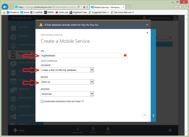
Type in your favorite service name, which has to be an unique identifier worldwide (as far I know).
About the database, ensure to pick the “Create a free 20 MB SQL database” (if you don’t have one yet), and the wizard will create automatically for you.
Two more parameters: select the closest region to you to host the service, then choose “JavaScript” as backend language for the management.

azure-mobile-create-service-2

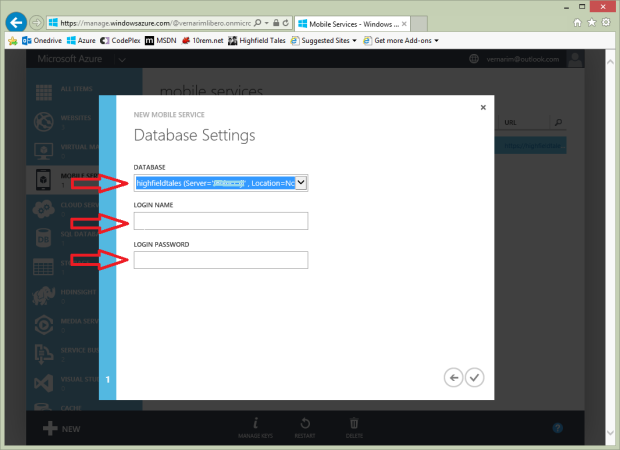
If you are creating a new database, you’ll face a second page in the wizard. Simply you have to specify the credentials to use to gain access to the database.

azure-mobile-create-service-3

That’s all: within a few your brand new mobile service should be ready. The below sample view gives an overview about the service.

Please, notice that there are links where you can download sample apps/templates already configured with your own parameters!…Dumb-proof!

azure-mobile-overview

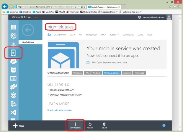
Also have a look at the bottom toolbar, where a “manage keys” button pops up some strange strings. Those strings are the ones that you should specify in the Netduino (and any other device) in order to gain access to the Azure Mobile Service.

        public static void Main()
        {
            //istantiate a new Azure-mobile service client
            var ms = new MobileServiceClient(
                "(your service name)",
                applicationId: "(your application-id)",
                masterKey: "(your master key)"
                );

The next task to do is about creating the database tables.
We need just three tables, and (even surprising) we don’t need to specify any column-schema: it will created automatically upon the JSON structure defined in the Netduino device software. This feature is by default, but you can disable it in the “configure” section, with the “dynamic schema” switch.

Table name Purpose
tdevices Each record is paired to a remote device and holds identification and status data of it.
tsensors Each record is paired to a “variable” defined by a certain device somewhere and holds identification and status data of it.
thistory Each record stores the value of a certain variable at the time it arrives on the server, or marks an event occurred. Think the table as a queue, where you can query the records in order to depict a certain variable’s value evolution over time.

azure-mobile-tables

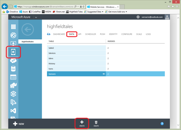
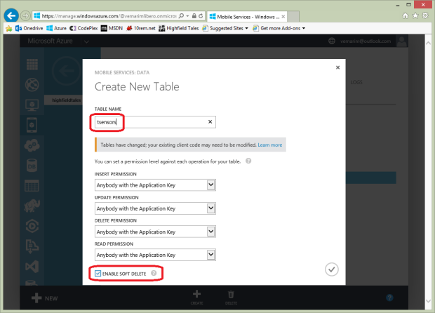
Press “create” and enter “tsensors”, then ensure checked the “enable soft delete” and confirm. Repeat the same for both the “tdevices” and the “thistory” tables, and your task is over.
The “soft delete” feature marks a record as “deleted” and keeps it, instead of removing from the table. You should enable this feature when you deal with concurrency. I personally think it is useful even for a simple dubugging. The problem is that is up to you “cleaning” the obsolete records.

azure-mobile-create-table

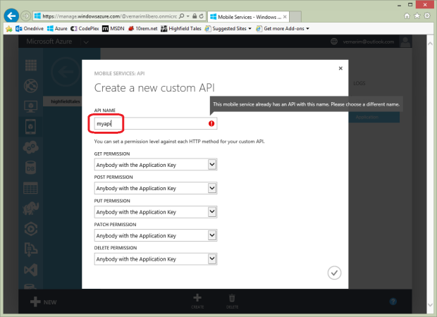
The last section to setup within the Mobile Service context is the “Custom API“, that is the code to run upon any incoming data request.
Simply select the “API” section, then press “create”.

azure-mobile-api-overview

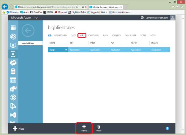
The wizard will ask you the name of the new API, as well as the permission grants to access it.
Back to the Netduino code, the API’s name should be specified on any request.

                    //execute the query against the server
                    ms.ApiOperation(
                        "myapi",
                        MobileServiceClient.Create,
                        jobj
                        );

Technically speaking, the name is the very last segment of the URI path which maps the request against Azure.

http://{your-service-name}.azure-mobile.net/api/{your-api-name}

azure-mobile-api-create

At this point you can begin to type the script in.

The device-side entry-point for the data.

The handler for the incoming requests is just a JavaScript function. Better: one function per HTTP method. However, since the primary goal is pushing data from a device into the server, the method used is POST (CREATE, in the REST terminology) all the times.
The JavaScript environment comes with Node.Js, which is very easy yet compact to use. I’m NOT a JavaScript addict, but honestly I didn’t have much effort in coding what I wanted.
The “script” section of the API allows to edit your script as you were on Visual Studio. The only missing piece is the Intellisense, but for JavaScript I don’t need it actually.

azure-mobile-api-script

The script we need is structured as follows:

exports.post = function(request, response) {

    // section: wake-up the webjob
        
    // section: update/insert the device's info into the "tdevices" table

    // section: update/insert the device's data into the "tsensors" table

    // section: append the device's data to the "thistory" table

};

Let’s face the database updating first.
For the “tdevices” table the script is as follows:

    var devicesTable = request.service.tables.getTable("tdevices");
    var sensorsTable = request.service.tables.getTable("tsensors");
    var historyTable = request.service.tables.getTable("thistory");
        
    //update/insert the device's info record
    devicesTable
    .where({
        devId: incomingData.devId
    }).read({
        success: function(results) {
            var deviceData = {
                devId: incomingData.devId,
                version: incomingData.ver
            };
            
            var flush = false;            
            if (results.length > 0) {
                //We found a record, update some values in it
                flush = (results[0].version != deviceData.version);
                results[0].devId = deviceData.devId;
                results[0].version = deviceData.version;
                devicesTable.update(results[0]);
                
                //Respond to the client
                console.log("Updated device", deviceData);
                request.respond(200, deviceData);
            } else {
                //Perform the insert in the DB
                devicesTable.insert(deviceData);

                //Reply with 201 (created) and the updated item
                console.log("Added new device", deviceData);
                request.respond(201, deviceData);
            }
            
            manageSensorTable(flush);
        }
    });    

As the data come in, the first thing is to look for the correspondent existent entry in the “tdevices” table, using the device’s identification as key. If the record does exist, it will be “updated”, otherwise a new entry will be added.
Upon an update, the logic here is comparing the incoming “configuration” version with the corresponding value stored in the table. If they don’t match, the “flush” flag is set, which serves to the next step to remove all the obsolete “sensor” entries.

When the operation on the “tdevices” table is over, begins the one on the “tsensors” and the “thistory” tables.
As in the previous snippet, first there is a selection of the records of “tsensors” marked as owned by the current device identifier. Then, if the “flush” flag is set, all the records are (marked as) deleted.
Finally, the data contained in the incoming message are scanned one item at once. For each variable, it looks for the corresponding entry in the recordset, then either update it or add a new record if wasn’t found.
Any item present in the message is also appended “as-is” to the “thistory” table.

    //update/insert the device's data record
    function manageSensorTable(flush) {
        sensorsTable
        .where({
            devId: incomingData.devId
        }).read({
            success: function(results) {
                if (flush) {
                    //flush any existent sensor record related to the involved device
                    console.log("Flush sensors data");
                    for (var i = 0; i < results.length; i++) {
                        sensorsTable.del(results[i].id);
                    }
                }
                
                for (var i = 0; i < incomingSensorArray.length; i++) {
                    var sensorData = {
                        devId: incomingData.devId,
                        name: incomingSensorArray[i].name, 
                        value: incomingSensorArray[i].value
                    };
                    
                    //find the index of the related sensor
                    var index = flush ? 0 : results.length;
                    while (--index >= 0) {
                        if (results[index].name == sensorData.name)
                            break;
                    }
                    
                    if (index >= 0) {
                        //record found, so update some values in it
                        results[index].devId = sensorData.devId;
                        results[index].name = sensorData.name;
                        results[index].value = sensorData.value;
                        sensorsTable.update(results[index]);
                    } else {
                        //Perform the insert in the DB
                        sensorsTable.insert(sensorData);
                    }
                    
                    //insert the record in the historian table
                    historyTable.insert(sensorData, {
                        success: function() {
                            //do nothing
                        }
                    });
                    
                }
            }
        });
    }

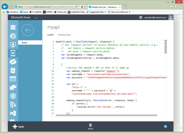
The last but not least piece of script is for waking up the webjob.
Please, note that my usage of the webjob is rather uncommon, but I think it’s the best compromise. The trade is between the Azure “free-context” limitations, and the desired service availability. The result is a webjob configured as “running continuously”, but is shut down by the platform when there’s no external “stimulation”. The trick is to “wake up” the webjob only when necessary by invoking a fake call to its site.
Have a look at my question on StackOverflow on how to solve the problem.

    {
        //access the webjob's API so that it'll wake up
        var wakeup_request = require('request');
        var username = "azureveneziano\$azureveneziano";
        var password = "(web-site-password)";
    
        var uri = 
            "http://" + 
            username + ":" + password + "@" +
            "azureveneziano.scm.azurewebsites.net/api/jobs/";
            
        wakeup_request(uri, function(error, response, body) {
            if (error) {
                console.error("scm failed:", error);
            }
        });
    }

At the end, it’s a trivial dummy read to the webjob deployment site. This read wakes up or keeps awaken the webjob.

Please, notice that all the “console” calls are useful only during the debugging stage: you should remove them when the system is stable enough.

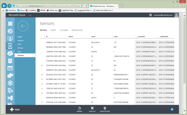
If everything goes well, the Netduino should send some data to the Azure API, and the database should fill.
Here is an example of what the “tsensors” table may contain:

azure-mobile-table-data

Creating and deploying the webjob.

To understand what a “webjob” is, I suggest to read the Scott Hanselman’s article.
Since a webjob is part of a web-site, you must create one first. Azure offers up to 10 web-sites for free, so that isn’t a problem. At the moment, I don’t use any “real” web-site (meaning pages), but I need the registration.
The procedure of registration, deployment and related task can be easily managed from within Visual Studio.

When I started the project I used Visual Studio Express 2013 for Web, and the Update 4 CTP allowed such a management. Since a few days, there’s another great alternative: Visual Studio 2013 Community, which comes out with Update 4 released, but offers also a lot of useful features.
The following snapshots were taken on the Express release, but should be similar on other editions.

Start Visual Studio and create a “Microsoft Azure Webjob” project, and give it the proper name.

webjob-wizard

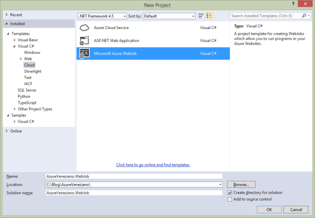
As you may notice, the solution composition looks almost the same as a normal Console application.
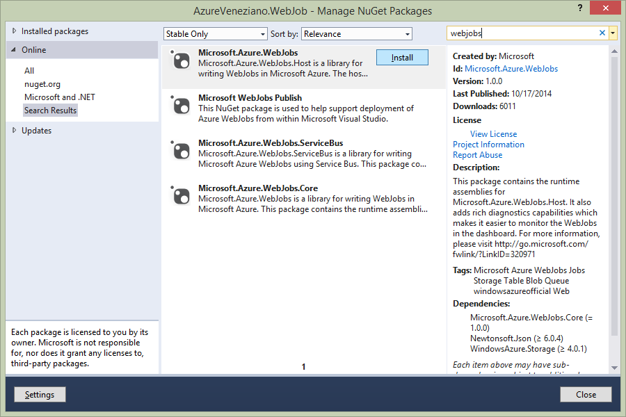
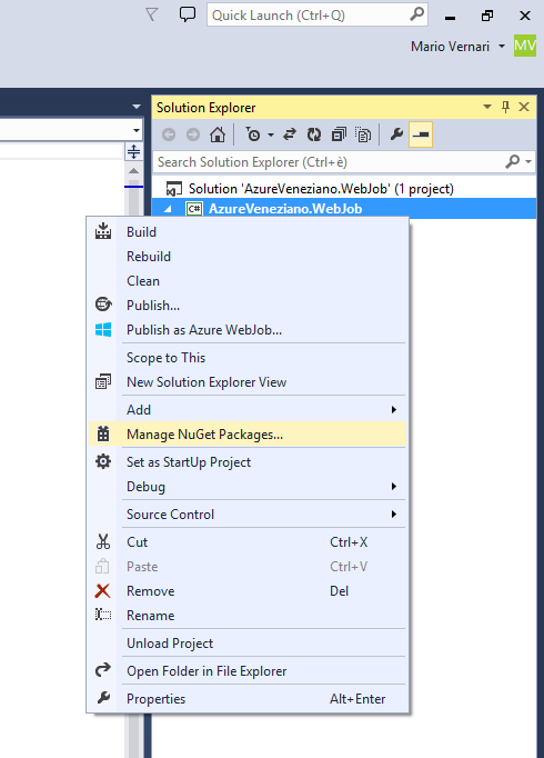
In order to add the proper references, just choose the “Manage NuGet packages” from the project’s contextual menu.

webjob-nuget-menu

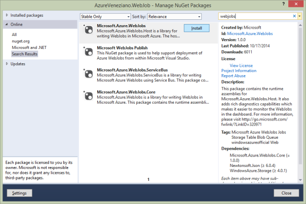
Firstly install the base “Microsoft.Azure.Webjobs” package as follows:

webjob-nuget-webjobs

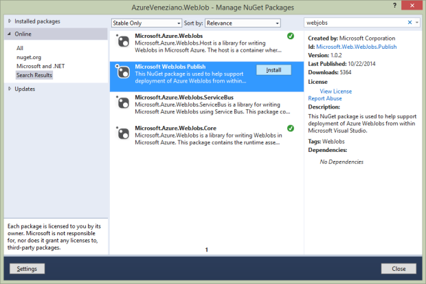
Then install the “Microsoft Webjobs Publish” package:

webjob-nuget-publish

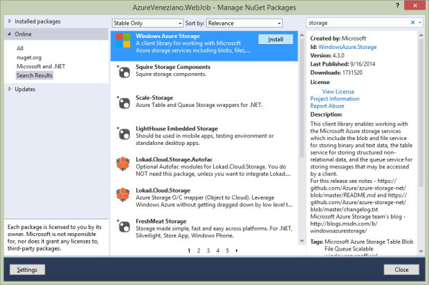
Finally install the “Windows Azure Storage” package:

webjob-nuget-storage

Since this webjob will “run continuously”, but will be actually shut down often, the very first thing to add to the code is a procedure for detecting the shutting request, so that to exit the application gracefully.
This piece of code isn’t mine, so I invite to read the original article by Amit Apple about the trick.

            #region Graceful-shutdown watcher

            /**
             * Implement the code for a graceful shutdown
             * http://blog.amitapple.com/post/2014/05/webjobs-graceful-shutdown/
             **/

            //get the shutdown file path from the environment
            string shutdownFile = Environment.GetEnvironmentVariable("WEBJOBS_SHUTDOWN_FILE");

            //set the flag to alert the incoming shutdown
            bool isRunning = true;

            // Setup a file system watcher on that file's directory to know when the file is created
            var fileSystemWatcher = new FileSystemWatcher(
                Path.GetDirectoryName(shutdownFile)
                );

            //define the FileSystemWatcher callback
            FileSystemEventHandler fswHandler = (_s, _e) =>
            {
                if (_e.FullPath.IndexOf(Path.GetFileName(shutdownFile), StringComparison.OrdinalIgnoreCase) >= 0)
                {
                    // Found the file mark this WebJob as finished
                    isRunning = false;
                }
            };

            fileSystemWatcher.Created += fswHandler;
            fileSystemWatcher.Changed += fswHandler;
            fileSystemWatcher.NotifyFilter = NotifyFilters.CreationTime | NotifyFilters.FileName | NotifyFilters.LastWrite;
            fileSystemWatcher.IncludeSubdirectories = false;
            fileSystemWatcher.EnableRaisingEvents = true;

            Console.WriteLine("Running and waiting " + DateTime.UtcNow);

            #endregion

At this point you might add some blocking code, and test what happens. As in the Amit’s article:

       // Run as long as we didn't get a shutdown notification
        while (isRunning)
        {
            // Here is my actual work
            Console.WriteLine("Running and waiting " + DateTime.UtcNow);
            Thread.Sleep(1000);
        }

        Console.WriteLine("Stopped " + DateTime.UtcNow);

Before deploying the webjob onto Azure, we should check the “webjob-publish-settings” file which is part of the project. Basically, we should adjust the file in order to instruct the server to run the webjob continuously. Here is an example:

{
  "$schema": "http://schemastore.org/schemas/json/webjob-publish-settings.json",
  "webJobName": "AzureVenezianoWebJob",
  "startTime": null,
  "endTime": null,
  "jobRecurrenceFrequency": null,
  "interval": null,
  "runMode": "Continuous"
}

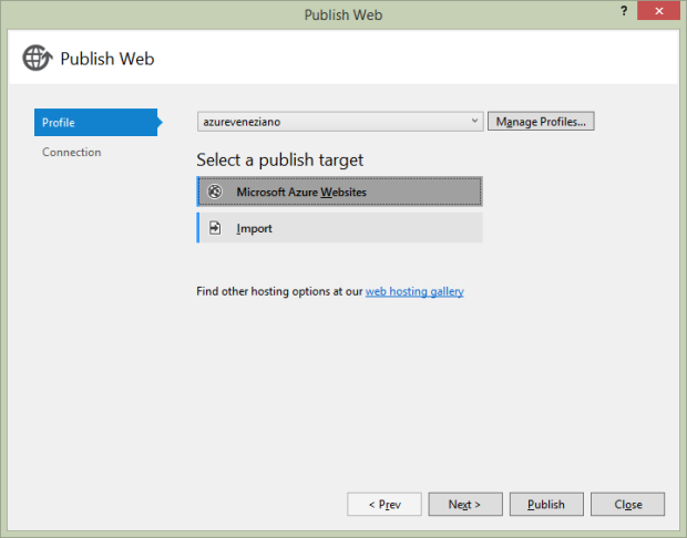
Open the project’s contextual menu, and choose the “Publish as Azure Webjob” item. A wizard like this one will open:

webjob-publish-0

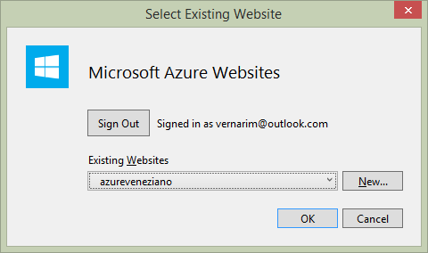
We should specify the target web-site from this dialog:

website-select

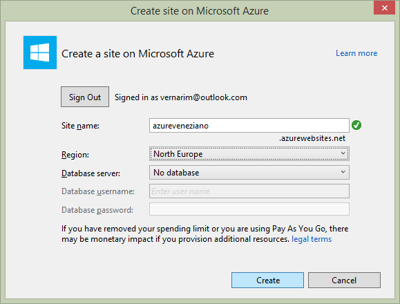
If the web-site is not existent yet, we should create a new one:

website-create

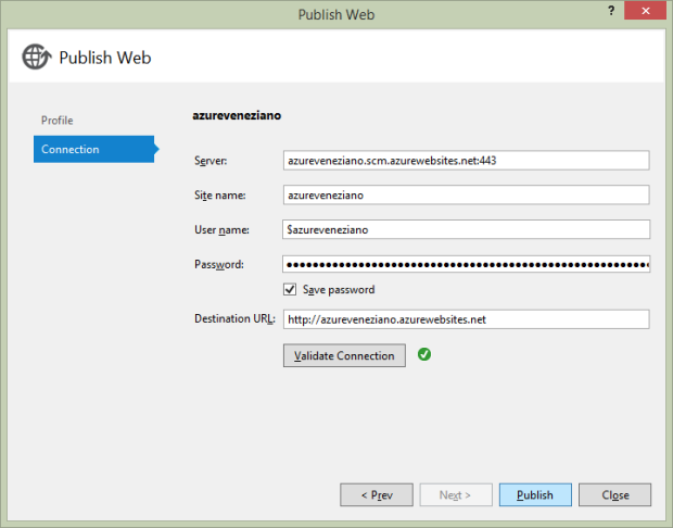
When everything has been collected for the deployment, we can validate the connection, then proceed to the publication.

webjob-publish-2

Once the webjob has been published, it should placed to run immediately. To test whether the shut down will happen gracefully, simply leave the system as is, and go to take a cup of coffee. After 20-30 minutes, you can check what really happened in the webjob’s log.

Please, note that it’s important that you leave any webjobs’ status page of the Azure portal during the test. It would hold alive the service without really shutting it down.

Enter in the “websites” category, then in the “Webjobs” section:

webjob-status

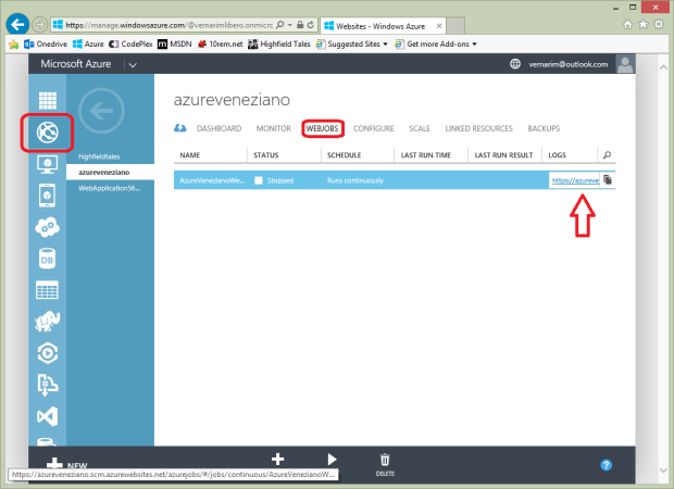
At this point you should see the status as “running” or being changing to. Click the link below the “LOGS” column, and a special page will open:

webjob-log

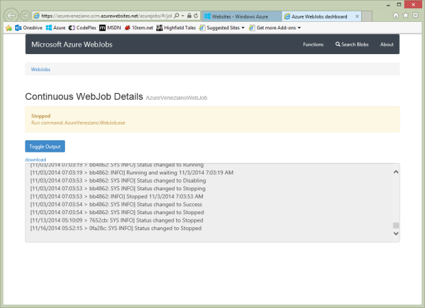
This mini-portal is a really nice diagnostic tool for the webjobs. You should able to trace both explicit “Console” logs and also exceptions. To reveal the proper flow of the webjob, you should check the timestamps, as well as the messages such as:

[11/03/2014 07:03:53 > bb4862: INFO] Stopped 11/3/2014 7:03:53 AM

The mail alert application.

Most of the material inherent to this article has been shown. However, I just would to close this part with a “concrete” sign of what the project should do. On the next article I’ll focus almost entirely on the webjob code, where the system could considered finished (many things will follow, though).

As described above, as soon a message from any device calls the API, the webjob is waken up (in case is stopped), and the data are pushed in the database.
The webjob task should pick those data out, and detect what is changed. However, the API and the webjob execution are almost asynchronous each other, so it’s better to leave the webjob running and polling for other “news”. On the other hands, when something changes by a remote point, it might be possible that something else will change too in a short time. This is another reason for leaving the webjob running until the platform shuts it down.

I don’t want to dig into details here: this will be argument for the next article. The only important thing is how the data are read periodically (about 10 seconds here) from the server. The data read are copied in a local in-memory model, for ease of interaction with the language.
At the end of each poll, the variable which are changed since the previous poll are marked with the corresponding flag. Immediately after, the program flow yields the execution of a custom logic, that is what the system should do upon a certain status.

        private const string connectionString =
            "Server=tcp:(your-sqlserver-name).database.windows.net,1433;" +
            "Database=highfieldtales;" +
            "User ID=(your-sqlserver-username);" +
            "Password=(your-sqlserver-password);" +
            "Trusted_Connection=False;" +
            "Encrypt=True;" +
            "Connection Timeout=30;";

        static void Main()
        {
            // ...

            //create and open the connection in a using block. This 
            //ensures that all resources will be closed and disposed 
            //when the code exits. 
            using (var connection = new SqlConnection(connectionString))
            {
                //create the Command object
                var command = new SqlCommand(
                    "SELECT * FROM highfieldtales.tsensors WHERE __deleted = 0",
                    connection
                    );

                //open the connection in a try/catch block.  
                //create and execute the DataReader, writing the result 
                //set to the console window. 
                try
                {
                    connection.Open();

                    //run as long as we didn't get a shutdown notification
                    int jobTimer = 0;
                    while (isRunning)
                    {
                        if (++jobTimer > 10)
                        {
                            jobTimer = 0;

                            //extract all the variables from the DB table
                            using (SqlDataReader reader = command.ExecuteReader())
                            {
                                while (reader.Read())
                                {
                                    /**
                                     * update the local in-memory model with the
                                     * data read from the SQL database
                                     */

                                }
                            }

                            //detect the most recent update timestamp as the new reference
                            foreach (LogicVar lvar in MachineStatus.Instance.Variables.Values)
                            {
                                if (lvar.LastUpdate > machine.LastUpdate)
                                {
                                    machine.LastUpdate = lvar.LastUpdate;
                                }
                            }

                            //invoke the custom logic
                            logic.Run();
                        }

                        Thread.Sleep(1000);
                    }
                }
                catch (Exception ex)
                {
                    Console.WriteLine(ex.Message);
                }
            }

            // ...
        }

Let’s say that this piece of code is “fixed”. Regardless what the system should react upon the status, this section will be always the same. For this reason there’s a special, well-defined area where we could write our own business logic.
Here is a very simple example:

    class CustomLogic
        : ICustomLogic
    {

        public void Run()
        {
            LogicVar analog0 = MachineStatus.Instance.Variables["Analog0"];
            LogicVar analog1 = MachineStatus.Instance.Variables["Analog1"];

            if ((analog0.IsChanged || analog1.IsChanged) &&
                (double)analog0.Value > (double)analog1.Value
                )
            {
                var mail = new MailMessage();
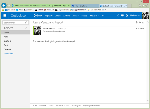
                mail.To.Add("vernarim@outlook.com");
                mail.Body = "The value of Analog0 is greater than Analog1.";
                MachineStatus.Instance.SendMail(mail);
            }
        }

    }

If you remember, the “Analog0” and “Analog1” are two variables sent by the Netduino. When I turn the trimpots so that:

  • any of the two variables is detected as changed, and…
  • the “Analog0” value becomes greater than the “Analog1” value…

…then an e-mail message is created and sent to me…(!)

Here is what I see on my mailbox:

mail-message

Conclusions.

This article looks long, but it isn’t actually so: there are a lot of picture because the Azure setup walkthrough.
Azure experts may say that a more straightforward solution would be using a Message-Hub instead of a tricky way to trigger a webjob. Well, yes and no. I didn’t find a way to “peek” what’s inside a queue without removing its content, as long as other problems to solve.
This is much more an experimental project built on the Azure “sandbox”, than a definitive optimal way to structure a telemetry system. However, I believe that’s a very good point to start, take practice, then refine your own project.

In the next article, I’ll show how to create a better (yet useful) mail alerting component.

Azure Veneziano – Part 1

Microsoft Azure logo

This is the the first part of a series, where I’ll present a telemetry project as a classic “Internet of Things” (IoT) showcase. The project starts as very basic, but it’ll grow up in the next parts by adding several useful components.
The central-role is for Microsoft Azure, but other sections will space over several technologies.

The source of the project is hosted in the azure-veneziano GitHub repository.

Inspiration.

This project was born as a sandbox for digging into cloud technologies, which may applies to our control-systems. I wanted to walk almost every single corner of a real control-system (kinda SCADA, if you like), for understanding benefits and limitations of a full-centralized solution.
By the way, I was also inspired by my friend Laurent Ellerbach, who published a very well-written article on how to create your own garden sprinkler system. Overall, I loved the mixture of different components which can be “glued” (a.k.a. interconnected) together: it seems that we’re facing a milestone, where the flexibility offered by those technologies are greater than our fantasy.
At the time of writing, Laurent is translating his article from French to English, so I’m waiting for the new link. In the meantime, here’s an equivalent presentation who held in Kiev, Ukraine, not long ago.

UPDATE: the Laurent’s article is now available here.

Why the name “Azure Veneziano”?

If any of you had the chance to visit my city, probably also saw in action some of the famous glass-makers of Murano. The “Blu Veneziano” is a particular tone of blue, which is often used for the glass.
I just wanted to honor Venezia, but also mention the “color” of the framework used, hence the name!

The system structure.

The system is structured as a producer-consumer, where:

  • the data producer is one (or more) “mobile devices”, which sample and sometime collect data from sensors;
  • the data broker, storage and business layer are deployed on Azure, where the main logic works;
  • the data consumers are both the logic and the final user (myself in this case), who monitor the system.

In this introductory article I’ll focus the first section, using a single Netduino Plus 2 board as data producer.

Netduino as the data producer.

In the IoT perspective, the Netduino plays the “Mobile device” role. Basically, it’s a subject which plays the role of a hardware-software thin-interface, so that the converted data can be sent to a server (Azure, in this case). Just think to a temperature sensor, which is wired to an ADC, and a logic gets the numeric value and sends to Azure. However, here I won’t detail a “real-sensor” system, rather a small simulation as anyone can do in minutes.
Moreover, since I introduced the project as “telemetry”, the data flow is only “outgoing” the Netduino. It means that there’s (still) no support to send “commands” to the board. Let’s stick to the simpler implementation possible.

The hardware.

The circuit is very easy.

netduino_bb

Two trimpots: each one provide a voltage swinging from 0.0 to 3.3 V to the respective analog input. That is, the Netduino’s internal ADC will convert the voltage as a floating-point (Double) value, which ranges from 0.0 to 100.0 (for sake of readiness, meaning it as it were a percent).
There are also two toggle-switches. Each one is connected to a discrete (Boolean) input, which should be configured with an internal pull-up. When the switch is open, the pull-up resistor takes the input value to the “high” level (true). When the switch is closed to the ground, it takes the value to the “low” level, being its resistance lower than the pull-up. and two switches.
If you notice, there’s a low-value resistor in series to each switch: I used a 270 Ohms-valued, but it’s not critical at all. The purpose is just to protect the Netduino input from mistakes. Just imagine a wrong setting of the pin actually configured as an output: what if the output would set the high-level when the switch is closed to the ground? Probably the output won’t fry, but the stress on that port isn’t a good thing.

All those “virtual” sensors can be seen from a programmer perspective as two Double- and two Boolean-values. The funny thing is that I can modify their value with my fingers!

???????????

Again, no matter here what could be the real sensor. I’d like to overhaul the hardware section for those who don’t like/understand so much about electronics. There are many ready-to-use modules/shields to connect, which avoid (or minimize) the chance to deal with the hardware.

Some virtual ports and my…laziness.

Believe me, I’m lazy.
Despite I’m having a lot of fun by playing with those hardware/software things, I really don’t like to stay spinning all the time the trimpots or sliding the switches, but I need some data changing overtime. So, I created a kind of (software) virtual port.
This port will be detailed below, and its task is to mimic a “real” hardware port. From the data production perspective it’s not different from the real ports, but way easier to manage, especially in a testing/demo session.
This concept of the “virtual port” is very common even in the high-end systems. Just think to a diagnostic section of the device, which collects data from non-physical sources (e.g. memory usage, cpu usage, etc)

The software.

Since the goal is posting on a server the data read by the Netduino, we should carefully choose the best way to do it.
The simplest way to connect a Netduino Plus 2 to the rest of the world is using the Ethernet cable. That’s fine, at least for the prototype, because the goal is reach the Internet.
About the protocol, among the several protocols available to exchange data with Azure, I think the simplest yet well-known approach is using HTTP. Also bear in mind that there’s no any “special” protocol in the current Netduino/.Net Micro Framework implementation.
The software running in the board is very simple. It can be structured as follows:

  • the main application, as the primary logic of the device;
  • some hardware port wrappers as data-capturing helpers;
  • a HTTP-client optimized for Azure-mobile data exchange;
  • a JSON DOM with serialization/deserialization capabilities;

The data transfer is normal HTTP. As the time of writing, the .Net Micro-Framework still did not offer any HTTPS support, so the data are flowing unsecured.

The first part of the main application is about the ports definition. It’s not particularly different than the classic declaration, but the ports are “wrapped” with a custom piece of code.

        /**
         * Hardware input ports definition
         **/

        private static InputPortWrapper _switch0 = new InputPortWrapper(
            "Switch0",
            Pins.GPIO_PIN_D0
            );

        private static InputPortWrapper _switch1 = new InputPortWrapper(
            "Switch1",
            Pins.GPIO_PIN_D1
            );

        private static AnalogInputWrapper _analog0 = new AnalogInputWrapper(
            "Analog0",
            AnalogChannels.ANALOG_PIN_A0,
            100.0,
            0.0
            );

        private static AnalogInputWrapper _analog1 = new AnalogInputWrapper(
            "Analog1",
            AnalogChannels.ANALOG_PIN_A1,
            100.0,
            0.0
            );

The port wrappers.

The aims of the port wrappers are double:

  • yield a better abstraction over a generic input port;
  • manage the “has-changed” flag, especially for non-discrete values as the analogs.

Let’s have a peek at the AnalogInputWrapper class, for instance:

    /// <summary>
    /// Wrapper around the standard <see cref="Microsoft.SPOT.Hardware.AnalogInput"/>
    /// </summary>
    public class AnalogInputWrapper
        : AnalogInput, IInputDouble
    {
        public AnalogInputWrapper(
            string name,
            Cpu.AnalogChannel channel,
            double scale,
            double offset,
            double normalizedTolerance = 0.05
            )
            : base(channel, scale, offset, 12)
        {
            this.Name = name;

            //precalculate the absolute variation window 
            //around the reference (old) sampled value
            this._absoluteToleranceDelta = scale * normalizedTolerance;
        }

        private double _oldValue = double.NegativeInfinity; //undefined
        private double _absoluteToleranceDelta;

        public string Name { get; private set; }
        public double Value { get; private set; }
        public bool HasChanged { get; private set; }

        public bool Sample()
        {
            this.Value = this.Read();

            //detect the variation
            bool hasChanged =
                this.Value < (this._oldValue - this._absoluteToleranceDelta) ||
                this.Value > (this._oldValue + this._absoluteToleranceDelta);

            if (hasChanged)
            {
                //update the reference (old) value
                this._oldValue = this.Value;
            }

            return (this.HasChanged = hasChanged);
        }

        // ...

    }

The class derives from the original AnalogInput port, but exposes the “Sample” method to capture the ADC value (Read method). The purpose is similar to a classic Sample-and-Hold structure, but there is a compare algorithm which detect the new value’s variation.
Basically, a “tolerance” parameter (normalized) has to be defined for the port (default is 5%). When a new sample is performed, its value is compared in reference to the “old value”, plus the tolerance-window around the old-value itself. When the new value falls outside the window, the official port’s value is marked as “changed”, and the old-value replaced with the new one.
This trick is very useful, because allows to avoid useless (and false) changes of the value. Even a little noise on the power rail can produce a small instability over the ADC nominal sampled value. However, we need just a “concrete” variation.

The above class implements the IInputDouble interface as well. This interface comes also from another, more abstract interface.

    /// <summary>
    /// Double-valued input port specialization
    /// </summary>
    public interface IInputDouble
        : IInput
    {
        /// <summary>
        /// The sampled input port value
        /// </summary>
        double Value { get; }
    }


    /// <summary>
    /// Generic input port abstraction
    /// </summary>
    public interface IInput
    {
        /// <summary>
        /// Friendly name of the port
        /// </summary>
        string Name { get; }

        /// <summary>
        /// Indicate whether the port value has changed
        /// </summary>
        bool HasChanged { get; }

        /// <summary>
        /// Perform the port sampling
        /// </summary>
        /// <returns></returns>
        bool Sample();

        /// <summary>
        /// Append to the container an object made up
        /// with the input port status
        /// </summary>
        /// <param name="container"></param>
        void Serialize(JArray container);
    }

Those interfaces yield a better abstraction over the different kinds of port: AnalogInput, InputPort and RampGenerator.

The RampGenerator as virtual port.

As mentioned earlier, there’s a “false-wrapper” because it does NOT wrap any port, but it WORKS as it were a standard port. The benefit become from the interfaces abstraction.
In order to PRODUCE data overtime for the demo, I wanted something automatic but also “well-known”. I may have used a random-number generator, but…how to detect an error or a wrong sequence over a random stream of numbers? Better to rely on a perfectly shaped wave, being periodic, so I can easily check the correct order of the samples on the server, but any missing/multiple datum as well.
As a periodic signal you can choose whatever you want. A sine is maybe the most famous periodic wave, but the goal is testing the system, not having something nice to see. A simple “triangle-wave” generator, is just a linear ramp rising-then-falling, indefinitely.

    /// <summary>
    /// Virtual input port simulating a triangle waveform
    /// </summary>
    public class RampGenerator
        : IInputInt32
    {
        public RampGenerator(
            string name,
            int period,
            int scale,
            int offset
            )
        {
            this.Name = name;
            this.Period = period;
            this.Scale = scale;
            this.Offset = offset;

            //the wave being subdivided in 40 slices
            this._stepPeriod = this.Period / 40;

            //vertical direction: 1=rise; -1=fall
            this._rawDirection = 1;
        }

        // ...

        public bool Sample()
        {
            bool hasChanged = false;

            if (++this._stepTimer <= 0)
            {
                //very first sampling
                this.Value = this.Offset;
                hasChanged = true;
            }
            else if (this._stepTimer >= this._stepPeriod)
            {
                if (this._rawValue >= 10)
                {
                    //hit the upper edge, then begin to fall
                    this._rawValue = 10;
                    this._rawDirection = -1;
                }
                else if (this._rawValue <= -10)
                {
                    //hit the lower edge, then begin to rise
                    this._rawValue = -10;
                    this._rawDirection = 1;
                }

                this._rawValue += this._rawDirection;
                this.Value = this.Offset + (int)(this.Scale * (this._rawValue / 10.0));
                hasChanged = true;
                this._stepTimer = 0;
            }
            
            return (this.HasChanged = hasChanged);
        }

        // ...

    }

Here is how a triangle-wave looks in a scope (it’s a 100 Hz, just to give an idea).

UNIT0000

Of course, I may have used a normal bench wave-generator as a physical signal source, as in the snapshot right above. That would have been more realistic, but the expected wave period would have been too short (i.e. too fast) and the “changes” with consequent message upload too frequent. A software-based signal generator is well suited for very-long periods, like many minutes.

The HTTP client.

As described above, the data are sent to the server via normal (unsecured) HTTP. The Netduino Plus 2 does not offer any HTTP client, but some primitives which help to create your own.
Without digging much into, the client is rather simple. If you know how a basic HTTP transaction works, then you’ll have no difficulty to understand what the code does.

    /// <summary>
    /// HTTP Azure-mobile service client 
    /// </summary>
    public class MobileServiceClient
    {
        public const string Read = "GET";
        public const string Create = "POST";
        public const string Update = "PATCH";

        // ...

        /// <summary>
        /// Create a new client for HTTP Azure-mobile servicing
        /// </summary>
        /// <param name="serviceName">The name of the target service</param>
        /// <param name="applicationId">The application ID</param>
        /// <param name="masterKey">The access secret-key</param>
        public MobileServiceClient(
            string serviceName,
            string applicationId,
            string masterKey
            )
        {
            this.ServiceName = serviceName;
            this.ApplicationId = applicationId;
            this.MasterKey = masterKey;

            this._baseUri = "http://" + this.ServiceName + ".azure-mobile.net/";
        }

        // ..

        private JToken OperateCore(
            Uri uri,
            string method,
            JToken data
            )
        {
            //create a HTTP request
            using (var request = (HttpWebRequest)WebRequest.Create(uri))
            {
                //set-up headers
                var headers = new WebHeaderCollection();
                headers.Add("X-ZUMO-APPLICATION", this.ApplicationId);
                headers.Add("X-ZUMO-MASTER", this.MasterKey);

                request.Method = method;
                request.Headers = headers;
                request.Accept = JsonMimeType;

                if (data != null)
                {
                    //serialize the data to upload
                    string serialization = JsonHelpers.Serialize(data);
                    byte[] byteData = Encoding.UTF8.GetBytes(serialization);
                    request.ContentLength = byteData.Length;
                    request.ContentType = JsonMimeType;
                    request.UserAgent = "Micro Framework";
                    //Debug.Print(serialization);

                    using (Stream postStream = request.GetRequestStream())
                    {
                        postStream.Write(
                            byteData,
                            0,
                            byteData.Length
                            );
                    }
                }

                //wait for the response
                using (var response = (HttpWebResponse)request.GetResponse())
                using (var stream = response.GetResponseStream())
                using (var reader = new StreamReader(stream))
                {
                    //deserialize the received data
                    return JsonHelpers.Parse(
                        reader.ReadToEnd()
                        );
                };
            }
        }

    }

The above code derived from an old project, but here are actually just few lines of code of that release. However, I want to mention the source for who’s interested in.

As the Azure Mobile Services offer, there are two kind of APIs which can be called: table- (Database) and custom-API-operations. Again, I’ll detail those features on the next article.
The key-role is for the OperateCore method, which is a private entry-point for both the table- and the custom-API-requests. All Azure needs is some special HTTP-headers, which should contain the identification keys for gaining access to the platform.
The request’s content is just a JSON document, that is simple plain-text.

The main application.

When the program starts, first creates an instance of the Azure Mobile HTTP-Client (Zumo), then wraps all the port references within an array, for ease of management.
Notice that there are also two “special” ports called “RampGenerator”. In this demo there are two wave-generators with a period of 1200 and 1800 seconds, respectively. Their ranges are also slightly different, but just for less confusion in the data verification.
The ability to fit all the ports in a single array, then treat them as they were an unique entity is the benefit offered by the interfaces abstraction.

        public static void Main()
        {
            //istantiate a new Azure-mobile service client
            var ms = new MobileServiceClient(
                "(your service name)",
                applicationId: "(your application-id)",
                masterKey: "(your master key)"
                );

            //collect all the input ports as an array
            var inputPorts = new IInput[]
            {
                _switch0,
                _switch1,
                new RampGenerator("Ramp20min", 1200, 100, 0),
                new RampGenerator("Ramp30min", 1800, 150, 50),
                _analog0,
                _analog1,
            };

After the initialization, the program runs in a loop forever, and about every second all the ports are sampled. Upon any “concrete” variation, a JSON message is wrapped up with the new values, then sent to the server.

            //loops forever
            while (true)
            {
                bool hasChanged = false;

                //perform the logic sampling for every port of the array
                for (int i = 0; i < inputPorts.Length; i++)
                {
                    if (inputPorts[i].Sample())
                    {
                        hasChanged = true;
                    }
                }

                if (hasChanged)
                {
                    //something has changed, so wrap up the data transaction
                    var jobj = new JObject();
                    jobj["devId"] = "01234567";
                    jobj["ver"] = 987654321;

                    var jdata = new JArray();
                    jobj["data"] = jdata;

                    //append only the port data which have been changed
                    for (int i = 0; i < inputPorts.Length; i++)
                    {
                        IInput port;
                        if ((port = inputPorts[i]).HasChanged)
                        {
                            port.Serialize(jdata);
                        }
                    }

                    //execute the query against the server
                    ms.ApiOperation(
                        "myapi",
                        MobileServiceClient.Create,
                        jobj
                        );
                }

                //invert the led status
                _led.Write(
                    _led.Read() == false
                    );

                //take a rest...
                Thread.Sleep(1000);
            }

The composition of the JSON message is maybe the simplest part, because the Linq-way of my Micro-JSON library.
The led toggling is just a visual heartbeat-monitor.

The message schema.

In my mind, there should be more than just a single board. Better: a more realistic system should connect several devices, even different from each other. Then, each device should provide its own data, and all the data incoming into the server would compose a big-bunch of “variables”.
For this reason, it’s important to distinguish the data originating source, and a kind of “device-identification”, unique in the system, is included in every message.
Moreover, I’d think that the set of variables exposed by a device could be changed any time. For example, I may add some new sensors, re-arrange the input ports, or even adjust some data type. All that means the “configuration is changed”, and the server should be informed about that. That’s because there’s a “version-identification” as well.

Then are the real sensors data. It’s just an array of Javascript objects, each one providing the port (sensor) name and its value.
However, the array will include only the port marked as “changed”. This trick yields at least two advantages:

  • the message length carries only the useful data;
  • the approach is rather “loose-coupled”: the server synchronizes automatically.

Each variable serialization is accomplished by the relative method declared in the IInput interface. Here is an example for the analog port:

        public void Serialize(JArray container)
        {
            var jsens = new JObject();
            jsens["name"] = this.Name;
            jsens["value"] = this.Value;
            container.Add(jsens);
        }

Here is the initial message, which always carries all the values:

{
  "devId": "01234567",
  "ver": 987654321,
  "data": [
    {
      "name": "Switch0",
      "value": true
    },
    {
      "name": "Switch1",
      "value": true
    },
    {
      "name": "Ramp20min",
      "value": 0
    },
    {
      "name": "Ramp30min",
      "value": 50
    },
    {
      "name": "Analog0",
      "value": 0.073260073260073
    },
    {
      "name": "Analog1",
      "value": 45.079365079365
    }
  ]
}

After that, we can adjust the trimpots and the switches in order to produce a “change”. Upon any of the detected changes, a message is composed and issued:

Single change Multiple changes
{
  "devId": "01234567",
  "ver": 987654321,
  "data": [
    {
      "name": "Analog1",
      "value": 52.503052503053
    }
  ]
}
{
  "devId": "01234567",
  "ver": 987654321,
  "data": [
    {
      "name": "Switch1",
      "value": false
    },
    {
      "name": "Analog1",
      "value": 75.946275946276
    }
  ]
}

Conclusions.

It’s easy to realize that this project is very basic, and there are many sections that could be improved. For example, there’s no any rescue of the program when an exception is thrown. However, I wanted to keep the application at a very introductory level.
It’s time to wire your own prototype, because in the next article we’ll see how to set-up the Azure platform for the data elaboration.

Let’s dig into an issue of the FT232 chip

The FTDI FT232-family of chips are used everywhere. They offers a very compact way to interface an UART to an USB. As soon the USB devices started booming, the “huge” serial connectors began to disappear from our PC. However, many of us still needed a real-serial port, and FTDI had the genial idea to create a small chip to provide the conversion.

Our primary usage is RS485 to USB conversion, and we designed from scratch our adapter from the beginning. However, since we needed some extra features on the adapter itself, we added a small MCU together with the FT232 chip. Let’s say the “dirty work” of cleaning the noise incoming from the RS485 line was made by the MCU, then its result is sent through the FTDI chip to the PC, via USB. Our systems are typically placed in very noisy environment, long cabling, poor grounding and so away. For this reason, even dealing with a lot of noise, we had never particular problems with such a structure.
No problems so far…until the past week!

The problem.

Consider any protocol you like over a UART: it’s typically structured as a BOM (begin-of-message) and some kind of EOM (end-of-message).
Let’s take it easy, considering that there’s no noise in the message itself, but immediately before or after. That’s not an abuse, because the RS485 line is placed in a low-impedance state only during the byte transfer. When released it’s in a high-impedance state, and a lot of noise is appearing on the line.
So, what do you expect from a false byte (due to the noise) immediately after the useful message? I’d expect an error after, and maybe some random bytes after the data. By the way, since we’re using a well-defined BOM+EOM, we’re able to detect the start and the end of the message, then cut off any false byte before and after.
Our surprise was seeing the false bytes…in the middle!

For make you understand better the case, I take my old Arduino 2009 and simply plug it to my pc. It’s a original Arduino, without any hack, and the scope probes are just for inspecting what happens.

Image00001

The Arduino is running this very minimal sketch. It’s just sending a string of bytes, continuously, interleaving a short delay.
If you notice, the “noise” is intentionally placed right after the end of the stream, as a byte sent with the wrong parity. The expectation is receiving a “frame error”, but maybe the correct value.

/*
* test_uart.ino
*
* Created: 9/24/2014 5:43:55 AM
* Author: Mario
*/

#define PARITY true

void setup()
{
    pinMode(2, OUTPUT);
}

void loop()
{
    digitalWrite(2, true);
  
    Serial.begin(38400, SERIAL_8E1);
    delay(10);

    for (byte i = 0; i < 0x60; i++){
        Serial.write(i);
    }
    Serial.flush();
    delayMicroseconds(500);
    
#if PARITY
    Serial.begin(38400, SERIAL_8O1);
    Serial.write(0x12);
    Serial.flush();
#endif
    
    digitalWrite(2, false);
    delay(200);
}

Now, here is the counterpart running on the PC, which receives the data and logs them on a file (or on the console).

    class Program
    {
        const string FileName = @"C:\Temp\arduino_dump.txt";

        static void Main(string[] args)
        {
                bool exit = false;
                byte[] buffer = new byte[1024];

                using (var port = new SerialPort("COM3", 38400, Parity.Even, 8, StopBits.One))
                {
                    //port.ParityReplace = 0;
                    port.Open();
                    port.ErrorReceived += port_ErrorReceived;

                    while (exit == false)
                    {
                        int count = port.BytesToRead;
                        if (count > 0)
                        {
                            port.Read(buffer, 0, count);

                            var sb = new StringBuilder();
                            for (int i = 0; i < count; i++)
                            {
                                //if (buffer[i] == 0) Console.WriteLine();
                                //Console.Write("{0:X2} ", buffer[i]);
                                if (buffer[i] == 0) sb.AppendLine();
                                sb.AppendFormat("{0:X2} ", buffer[i]);
                            }

                            File.AppendAllText(FileName, sb.ToString());
                        }

                        if (Console.KeyAvailable)
                        {
                            exit = true;
                        }
                        else
                        {
                            Thread.Sleep(1);
                        }
                    }

                }
        }

        static void port_ErrorReceived(object sender, SerialErrorReceivedEventArgs e)
        {
            Console.WriteLine(e.EventType);
        }
    }

Image00002

console

When the programs run, the log collects the received data and it’s pretty clear where the problem is.


00 01 02 03 04 05 06 ... 4A 4B 4C 4D 4E 3F 3F 4F 50 51 52 53 54 55 56 57 58 59 5A 5B 5C 5D 5E 5F 12
00 01 02 03 04 05 06 ... 4A 4B 4C 4D 4E 4F 50 3F 3F 51 52 53 54 55 56 57 58 59 5A 5B 5C 5D 5E 5F 12
00 01 02 03 04 05 06 ... 4A 4B 4C 4D 4E 4F 3F 3F 50 51 52 53 54 55 56 57 58 59 5A 5B 5C 5D 5E 5F 12
00 01 02 03 04 05 06 ... 4A 4B 4C 4D 4E 4F 50 51 3F 3F 52 53 54 55 56 57 58 59 5A 5B 5C 5D 5E 5F 12

Note: the strings have been shorted for clarity.

As expected, the extra byte appears always at the end of each string: simply the FT232’s UART accepts the 8-bits value as-is, despite the wrong parity.
However, the real problem is before the extra byte: there is a strange 3F-pair in the message. Why? Who adds it?

Let’s dig into..

First off, the MSDN docs about the SerialPort state that the 3F is added by the framework, upon the ParityReplace property. That is, when this property is set to zero (disable parity replacing), the 3F-pair disappear. Yes, but I wouldn’t lose that info, and…why the parity error is revealed a bunch of bytes before the actual wrong byte?

My colleague made several tests:

  • a serial stream using the “old” RS232;
  • a serial stream using a commercial RS232-to-USB NOT-using a FTDI chip;
  • a serial stream using a commercial RS232-to-USB using a FTDI chip.

It was pretty easy to understand that the odd-placement of the 3F-pair was observed only in the FTDI case.

As he was performing the tests, I decided to make my own with the Arduino, which is shown above. However, I wanted to understand why, so I moved to some research.
FTDI does not offer any specs about the FT232 USB protocol. However, there’s always an angel in the sky, and this angel actually wrote a small C-library which claims to interface Windows/Linux without any problem to the FT232-family chips.
Browsing the driver sources, I bumped against the status poll, which also transfers the data from the chip to the pc.
Here is some remark found in the sources:

/**
    Poll modem status information

    This function allows the retrieve the two status bytes of the device.
    The device sends these bytes also as a header for each read access
    where they are discarded by ftdi_read_data(). The chip generates
    the two stripped status bytes in the absence of data every 40 ms.

    Layout of the first byte:
    - B0..B3 - must be 0
    - B4       Clear to send (CTS)
                 0 = inactive
                 1 = active
    - B5       Data set ready (DTS)
                 0 = inactive
                 1 = active
    - B6       Ring indicator (RI)
                 0 = inactive
                 1 = active
    - B7       Receive line signal detect (RLSD)
                 0 = inactive
                 1 = active

    Layout of the second byte:
    - B0       Data ready (DR)
    - B1       Overrun error (OE)
    - B2       Parity error (PE)
    - B3       Framing error (FE)
    - B4       Break interrupt (BI)
    - B5       Transmitter holding register (THRE)
    - B6       Transmitter empty (TEMT)
    - B7       Error in RCVR FIFO

So, something gets clearer:

  • The UART error are summarized as-per-chunck of data, not just for each byte;
  • the incoming data should face a bit-2 equals to ONE because the forced parity error.

I am FAR to be an expert of USB protocols, and of course you would have many USB devices exchanging data. Listening to what’s up in the circus may be a challenge.
The first thing to do is inspecting the Windows registry for the VID/PID codes of the FDTI chip. Here is how to do:

registry

To inspect the USB data, the simplest things to do is downloading the really awesome tool provided by Microsoft: Messaging Analyzer. It does almost everything (excluding coffee), and it’s also free.

ms-message-analyzer

In order to limit the number of the message displayed, but let’s apply a simple (even dumb) filter to the grid. The results are as follows.
This first picture shows the last chunk of the string when there’s NO the extra byte. You may notice that the status byte has the bit-2 off.

capture-ok

The second snapshot shows the altered transfer, instead. The status byte has now the bit-2 on.

capture-err

Conclusions.

The reason behind the odd-placement is now clear: a design-decision of the FTDI engineers. However, seems that there’s no way to overcome this problem. The only thing you can do is disabling the ParityReplace in the SerialPort, and forget any UART error. This imply you strictly rely the reliability of the message on the protocol itself, because the physical layer won’t help you much.

Netduino + FT800 Eve = MicroWPF

The spare time is few, but step by step the target is getting closer.
It’s a been I’ve started playing around the FTDI FT800 Eve board, and it must admit it is awesome. If you need a quick solution to add a small touch display to your *duino board, the Eve is something you should consider.

EVE image

You know, I love Netduino and C#. That’s because I chose to play with the display using Netduino (Plus 2), and honestly I’d expected a pretty bad performance. Instead, the graphic engine of the Eve can be easily driven via SPI from any board. That is, the SPI on Netduino is fast, very fast.

My goal is creating a small library for helping many users to create small and funny home/hobby projects with the Netduino and the Eve display boards. Since I love the classic WPF, how could I avoid to inspire from them?

Micro WPF

If you know WPF, many concepts would come easier. Otherwise, I recommend to take a look to the documentation, tutorials and whatever you want. Even if you don’t harm with a PC, rather with the Windows Store/Phone APIs, the approach here isn’t too far from.
The “WPF” term for a simple Netduino is clearly abused. Here is just the visual approach, the XAML-like approach to create the UI, and -yes- the same ability to create your own controls: MeasureOverride and ArrangeOverride.
That’s not all.
If you have any visual application in mind with Netduino+Eve (e.g. a climate control, IoT client, etc), then probably you’d need some kind of navigation service across several pages. That’s the most modern UI experience, on every device: PC, tablets, and phones.

I still don’t write what the library will offer, because it’s just something made for fun: for helping hobbists and even students working with a UI on a such small board as Netduino is.
For sure, there are NOT (nor in the future):

  • data binding
  • XAML parsing (the tree has to be created programmatically)
  • styling
  • the remaining 99.99% of regular WPF…

An example of layout

The most versatile yet complex layout control is the Grid, but it seems working fine.
Let’s take this sample XAML:

<Page x:Class="WpfApplication2.Page1"
      xmlns="http://schemas.microsoft.com/winfx/2006/xaml/presentation"
      xmlns:x="http://schemas.microsoft.com/winfx/2006/xaml"
      xmlns:mc="http://schemas.openxmlformats.org/markup-compatibility/2006" 
      xmlns:d="http://schemas.microsoft.com/expression/blend/2008" 
      mc:Ignorable="d" 
      d:DesignHeight="300" d:DesignWidth="300"
	Title="Page1">

    <Grid>
        <Grid.ColumnDefinitions>
            <ColumnDefinition Width="150" />
            <ColumnDefinition Width="*" />
            <ColumnDefinition Width="Auto" />
        </Grid.ColumnDefinitions>

        <Grid.RowDefinitions>
            <RowDefinition Height="*" />
            <RowDefinition Height="2*" />
            <RowDefinition Height="Auto" />
        </Grid.RowDefinitions>

        <StackPanel
            Grid.Row="0"
            Grid.Column="0"
            x:Name="R0C0"
            Background="Blue"
            />

        <StackPanel
            Grid.Row="0"
            Grid.Column="1"
            x:Name="R0C1"
            Background="DarkGreen"
            />

        <StackPanel
            Grid.Row="0"
            Grid.Column="2"
            x:Name="R0C2"
            Background="Red"
            >
            <Button
                Content="Caption"
                Width="120"
                Height="30"
                Margin="10,5"
                HorizontalAlignment="Center"
                x:Name="B0"
                />
        </StackPanel>


        <StackPanel
            Grid.Row="1"
            Grid.Column="0"
            Grid.ColumnSpan="2"
            x:Name="R1C0"
            Background="LightPink"
            />


        <StackPanel
            Grid.Row="2"
            Grid.Column="1"
            Grid.ColumnSpan="2"
            x:Name="R2C1"
            Background="MediumSlateBlue"
            >
            <Button
                Content="Caption"
                Width="120"
                Height="30"
                Margin="10,5"
                HorizontalAlignment="Center"
                x:Name="B2"
                />
        </StackPanel>

    </Grid>
</Page>

On the regular WPF the result is the following:

sample-wpf

Now, let’s see how to write the same thing on Netduino:

    public class DemoPage2 : PageBase
    {
        protected override void OnCreate(FT800Device dc)
        {
            var btn_prev = new WidgetButton() { Margin = new Thickness(10, 5), Text = "Prev" };
            btn_prev.Click += new EventHandler(btn_prev_Click);

            var btn_next = new WidgetButton() { Margin = new Thickness(10, 5), Text = "Next" };
            btn_next.Click += new EventHandler(btn_next_Click);
            btn_next.HAlign = HorizontalAlignment.Center;

            var grid = new WidgetGridContainer();
            grid.Name = "GRID";

            grid.AddColumnDefinition(150);
            grid.AddColumnDefinition(1, GridUnitType.Star);
            grid.AddColumnDefinition(1, GridUnitType.Auto);

            grid.AddRowDefinition(1, GridUnitType.Star);
            grid.AddRowDefinition(2, GridUnitType.Star);
            grid.AddRowDefinition(1, GridUnitType.Auto);

            {
                var ctr = new WidgetStackContainer();
                ctr.Name = "R0C0";
                ctr.Background = Colors.Blue;
                grid.SetRowCol(ctr, 0, 0);
                grid.Children.Add(ctr);

                ctr.Children.Add(btn_prev);
            }
            {
                var ctr = new WidgetStackContainer();
                ctr.Name = "R0C1";
                ctr.Background = Colors.DarkGreen;
                grid.SetRowCol(ctr, 0, 1);
                grid.Children.Add(ctr);
            }
            {
                var ctr = new WidgetStackContainer();
                ctr.Name = "R0C2";
                ctr.Background = Colors.Red;
                grid.SetRowCol(ctr, 0, 2);
                grid.Children.Add(ctr);

                ctr.Children.Add(
                    new WidgetButton() { Name = "B0", Margin = new Thickness(10, 5) }
                    );
            }
            {
                var ctr = new WidgetStackContainer();
                ctr.Name = "R1C0";
                ctr.Background = Colors.LightPink;
                grid.SetRowCol(ctr, 1, 0, 1, 2);
                grid.Children.Add(ctr);
            }
            {
                var ctr = new WidgetStackContainer();
                ctr.Name = "R2C1";
                ctr.Background = Colors.MediumSlateBlue;
                grid.SetRowCol(ctr, 2, 1, 1, 2);
                grid.Children.Add(ctr);

                ctr.Children.Add(btn_next);
            }

            this.Content = grid;
        }

        void btn_prev_Click(object sender, EventArgs e)
        {
            NavigationService.Instance.GoBack();
        }

        void btn_next_Click(object sender, EventArgs e)
        {
            NavigationService.Instance.Navigate(new DemoPage3());
        }
    }

That leads the following snapshot:

My Snapshot5

NOTE: by live the display shows the colors correctly. However, the picture taken renders a bad result.

Widgets, widgets, widgets…

The Eve board is very well designed, because it’s plenty of useful widgets. I don’t believe you’d need something different from the provided.
At the moment of writing, the Netduino library supports:

  • (normal) Button
  • ToggleButton
  • TextBlock
  • Slider
  • Dial

and, as for the layout control:

  • StackPanel
  • Grid

As long the spare time helps me, I will try to add some other useful component as the TextBox and the Image.

Yet some screens generated by the Netduino and the FT800 Eve board.
WP_000595

My Snapshot4

My Snapshot3

My Snapshot7

Source code

I will release a beta release soon.

Microsoft TechDays 2013 Paris: une grand merci!

The greatest Microsoft event of Europe has just been closed in Paris, France.
I am soooo honored to have been mentioned in the “Geek in da House” session of Laurent Ellerbach.

Image00001

He presented two very interesting projects, both of them involving Netduino and a little hardware around.
In the first part of his session, Laurent presents his remotely controlled gardening sprinkler system. Afterward, his Netduino is used in a totally different way: as transmitter for IR commands against a Lego train. My help was just on the latter project.
Here is the link of the video (French speaking).
Have fun!