This is my first post about Windows 10 IoT and small computers (embedded) after some experiences in the past with the .Net MicroFramework (Netduino, in essence).
I must say that this Windows 10 is finally a small masterpiece, or “everything you ever asked and none never responded you”. The programming way is easy but very flexible, although still many bricks are missing (in development).
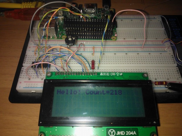
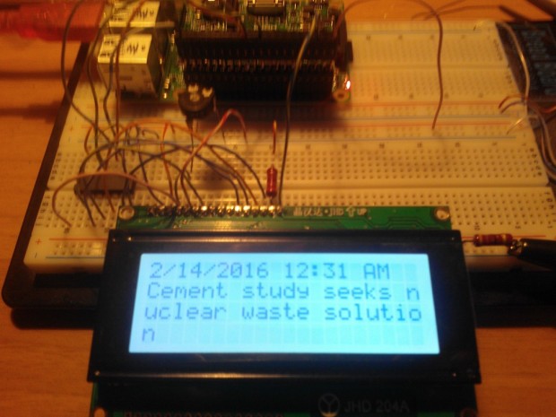
Here is a very simple experiment, a bit vintage, of driving a common alphanumeric LCD module (HD44780-based) with a Raspberry PI 2 and Windows 10 IoT.
The project isn’t anything new, but rather kinda “refresh” of another of mine where the Netduino board was used (see below). Someone of you may wonder “why” still using a so-old LCD module when several graphics are available on the market. Well, my first answer is: “why not?”. As said, this project hasn’t any specific purpose (although many of you may dig into their “miracles box” and pull out an “almost useless” LCD module). The aim is to test how hard is to drive something well known.
Some credits…
I can’t miss to mention Laurent Ellerbach, who gave me some inspiration (and motivation) on pursuing those hacking/funny activities.
The hardware.
All you need is very easy to find:
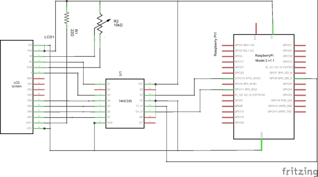
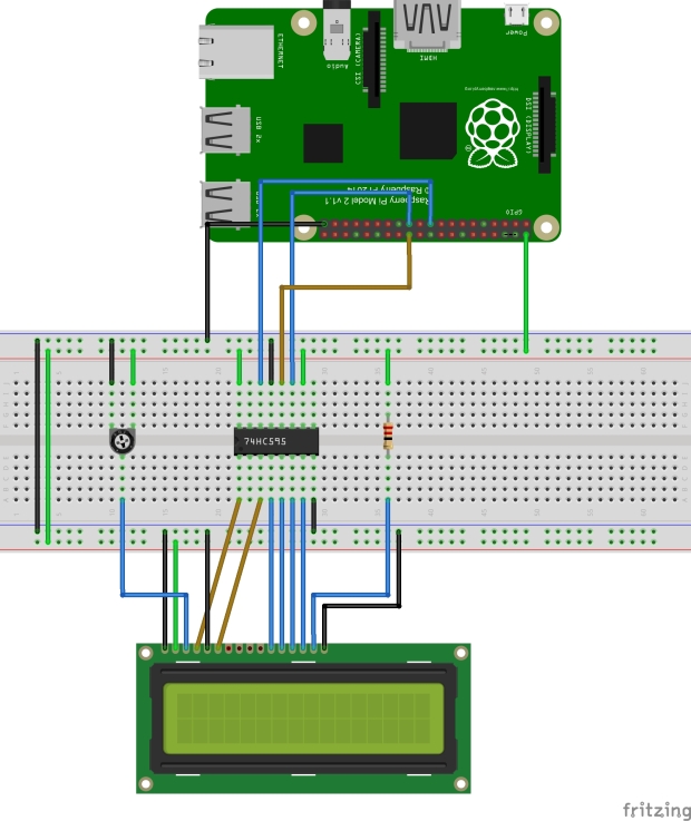
Raspberry PI2 (with Windows 10 IoT installed)
any suitable HD44780 LCD display module (mine is a 4×20)
74HC595 shift-register
220 Ohms resistor (only if you need the backlight)
10k Ohms trimpot (22k or 47k are fine the same)
For sake of simplicity, I won’t detail how to set up the Raspberry, but there are many articles which describe very well that. I followed the Microsoft site and everything went fine, except for the suggested SD minimum size: I found that a 8GB won’t work. Simply consider a 16GB.
The software.
I wanted to publish the project keeping the sources simpler as possible. A similar application won’t have sense in a complex hardware (full-featured TFT displays and HDMI monitors perform way better than this module). The general guideline is: if you find convenient to connect a LCD module to a RPI, then make it working in minutes.
Since the LCD module’s capabilities are very limited, I embraced the idea to expose the APIs as it were a kind of “Console”. Just a “write” and something more, where a background task should manage the physical transfer by itself.
The project contains two different demo:
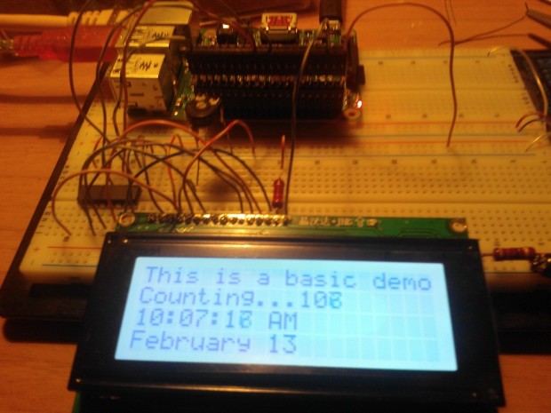
a basic one, where some strings’ content is reflected on the display;
a slightly more complex demo, which gets a bunch of RSS news from the BBC.uk channel, and rotates the titles on the screen.
Basic demo.
    class BasicDemo
    {

        public async Task RunAsync()
        {
            //write a static string
            DriverHD44780.Instance.DrawString(
                "This is a basic demo",
                new Point(0, 0)
                );

            int n = 0;
            while (true)
            {
                //display a simple counter
                DriverHD44780.Instance.DrawString(
                    $"Counting...{n}",
                    new Point(0, 1)
                    );

                //display current time and date
                var now = DateTime.Now;
                DriverHD44780.Instance.DrawString(
                    now.ToString("T") + "   ",
                    new Point(0, 2)
                    );

                DriverHD44780.Instance.DrawString(
                    now.ToString("M") + "   ",
                    new Point(0, 3)
                    );

                n++;
                await Task.Delay(1000);
            }
        }

    }
RSS demo.
    class RssDemo
    {

        public async Task RunAsync()
        {
            //write a static string
            DriverHD44780.Instance.DrawString(
                "Getting RSS...",
                new Point(0, 0)
                );

            //get the latest news using a normal HTTP GET request
            var http = new HttpClient();
            var endpoint = new Uri("http://feeds.bbci.co.uk/news/rss.xml");

            var srss = await http.GetStringAsync(endpoint);
            var xrss = XDocument.Parse(srss);

            //extract the news items, and sort them by date-time descending
            var xnews = xrss.Root
                .Element("channel")
                .Elements("item")
                .OrderByDescending(_ => (DateTime)_.Element("pubDate"))
                .ToList();

            int n = 0;
            while (true)
            {
                /**
                * Loop the news as one per page
                **/

                //the first row is for the publication date-time
                var dt = (DateTime)xnews[n].Element("pubDate");
                DriverHD44780.Instance.DrawString(
                    dt.ToString("g"),
                    new Point(0, 0)
                    );

                //the three other rows are for the title
                var title = (string)xnews[n].Element("title");
                title = title + new string(' ', 60);

                for (int row = 0; row < 3; row++)
                {
                    DriverHD44780.Instance.DrawString(
                        title.Substring(row * 20, 20),
                        new Point(0, row + 1)
                        );
                }

                //wait some seconds before flipping page
                n = (n + 1) % xnews.Count;
                await Task.Delay(3000);
            }
        }

    }
Performance.
You may wonder how well performs the driver. Well, there are two stages involved in the displaying process:
the calls from the main application to the driver;
the physical data transfer.
Any invokation by the main app involves always the cache: no matter how many calls are made, because everything is hosted in memory. For this reason, any manipulation is irrelevant in terms of performance impact. However, a fixed rate (typically 200ms) there’s a cache dump to the LCD screen, that is: the physical data transfer though the SPI.
How long takes the entire screen dump via SPI?
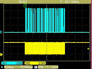
The circuit is very simple, thus there’s no way to take the transfer faster than the machine execution speed. Even adjusting the SPI clock rate, the resulting duration won’t change notably. Please, bear in mind that a too high SPI clock rate could face signal degradation due the wire length. I used a perfect 1 MHz value, and you can see from the below screenshot that the total transfer duration is less than 30ms.
If you are interested in a faster way to dump the data via SPI, I suggest to read the following section which requires a decent knowledge about electronics.
The old “LCD Boost” library.
The original project was tailored for the .Net MicroFramework (Netduino) and many things were optimized for speed reasons. Moreover, the NetMF had some leaky problems mostly due to the super squeezed CLR, thus many solutions were solved as it were a low-level device.
Here are some links to the original articles of mine:
This post was not planned, in the sense that the main article is expected on the real working project (coming soon), not on the problems related. However, this is a typical case of hardware malfunction (due to a insufficient design redundancy), and it thought it was useful to show. I realized that most users not having a good practice in electronics, get discouraged when they try to replicate a circuit and that does not work as expected. They first wonder about the “logical equivalency” of the schematic/wiring, but that does not seem a good reason for make it working.
Electronics is physics, I mean a small part of. So, the world is not working differently when we talk about electrons spinning or a logic chip connected to a micro-controller. However, the main task done for years by scientists is to simplify, to model, to minimize interaction between “electronic parts”, so that the design will become easier yet reliable.
Yesterday.
In this post I want to describe what happened to me yesterday, when I was trying to make the circuit working, but it did not wanted to. All my attention was payed on the software (written by me), on possible bugs in the new Netduino Plus 2, and even about some wrong wiring. None of these areas was the right one, but the most unsuspected component.
The goal of the project is interfacing a Sure Electronics Led-matrix board to the Netduino Plus 2 with a minimal external hardware. By the way, the board can be SPI-driven with a couple more of signals. All I need is some pull-up resistor, just because the STM32 MCU used by the Netduino Plus 2 does not embed them as the Atmel does.
So far, so well.
Yesterday the C# software driver was completed and worked well…ehm, bad…or well?…Hard to say how…
According to the Sure Electronics datasheet, as well as the Holtek HT1632 datasheet, my driver running on the Netduino produced the waveform correctly. Every single pattern, command, and data have been checked on the scope, and looked fine. However, the leds on the board were not lighting at all, or -at most- randomly colorized.
Today.
I had a suspect on the board itself, but I refused it because I mumbled:
…these boards are sold worldwide in thousands units: how can be not working?
However, today I checked the board correctness against its schematic.
The first yet easy component to check was the mapper for enabling the HT1632 led-controllers. There are four controllers on my board, which is 16 rows by 32 columns, bi-color led-matrix. The mapper is a normal 74HC164 shift-register, similar but simpler than the famous 74HC595.
The software driver clocks the 74HC164 so that only one HT1632 is enabled at once. Basically the driver issues a logic “zero” to the shift-register input, then shifts once: this will move the zero to the first register output, while all the remaining are “one”. This enables only the first controller, and the driver feeds it with the matrix data. Every further clock should issue a logic “one”, so that the logic “zero” is “moving” forward on the register’s outputs, and the other controllers are enabled. The 74HC164 used for enabling the led controllers.
What made me shocking is the wrong output state of the register. Although the clocks were issued correctly, as well as the input data, the outputs were completely wrong, most of the times enabling more controllers at once. That was a very good reason for the leds lighting randomly!
So, my move was to inspect what made the shift-register shifting unexpectedly. To do that, I placed the first scope probe on the 74HC164 output activating badly, and the second probe on the same chip clock. At first glance there was no reason for the output getting low, because there was no clock edges. However, something must happen, because the 74HC164 actually shifts the data. The 74HC164 clock (above) and the data input fed into.
The first output of the shift-register, which correctly goes low along a whole clock period.The shifter’s second output going low earlier than the second clock pulse.The clock generated by the Netduino is perfectly flat upon the output falling: that’s suspect!
The driver timings are around several milliseconds: even the new Netduino can’t reach microseconds pulses. By the way, the external logic does not care about milliseconds, and it works even on nanoseconds events.
The actual clock by the 74HC164 pin shows a small glitch shorter than 100nS.
I scaled the scope time-base up to sub-microseconds timings, and…GOTCHA!…a subtle pulse was causing the improper shifting.
Now, I didn’t know exactly where that pulse is originated, nor the very best way to avoid it. By the way, it had to cut off, otherwise the board won’t worked. Two guesses: stray capacitance (e.g. PCB tracking too tight), and/or bad grounding (e.g. leds’ current leads voltage drops).
The solution.
The easier way to cut a spike off is placing a small 1nF capacitor across the signal and ground (assuming the grounding is good). The 1nF capacitor added to the board.
The funny thing is that the capacitor was considered by design, but not mounted (at least on my board). I wonder why the Sure Electronics Engineers missed it.
The 74HC164 second output shows perfectly after the capacitor insertion.
Conclusions.
I know, it’s frustrating.
Most of the users having fun with Netduino are programmers, and they can’t accept that does not exist “copy-and-paste” for hardware. Well, it can be applied if the circuit model has enough redundancy so that most of the undesired effects and interactions can be ignored.
So, please, don’t trash your long awaited hardware project just because it does not work at first time. Dig, dig, and dig again. Also remember that a logic analyzer can’t replace a scope, but a scope most of the time can.
Time ago, Stanislav -a Netduino community user- posted a problem on how to drive a 6-by-4 led-matrix using its Netduino. After some experiment, he got stuck with the circuit, because a matrix must be multiplexed, and that’s not easy to solve.
Here is the link to the forum thread.
If you read the message exchange on the thread, then you’ll collect easily a list of constraints. Here they are:
the leds have been already assembled (i.e. only the multiplex driver is needed)
the overall price should fall within 10 Euro
must be handcrafted, thus no use of small parts (e.g. SMDs)
the multiplex should not stop its cycling as the Netduino stops (avoid leds burnout)
the circuit should avoid complicate wiring, so that the PCB can get pretty easy
reliable enough
finally, Stanislav asked to learn how to design such a circuit
It was clear that Netduino only wasn’t enough to drive a 6×4 led-matrix. First off, for the inability to give enough current for the leds, and secondly for the relative slowness of the managed code running into.
The problem in depth.
Light up a led is very simple. Starting from the power supply, as parameter you have the current flowing through the led, then calculating the resistor to put in series. A led needs from few mA (SMDs), to several hundreds of mA (or even more) for the high-power class.
Let’s face the multiplex problem thinking to a normal discrete-led which needs 10 mA for a normal brightness.
So, what is a multiplex?
The multiplexing is a technique for driving many loads (e.g. leds), using a relatively low number of wires. Thinking to a 6×4 led-matrix, instead having 24 wires (one for each led), the multiplex-way needs only 6+4 = 10 wires at all. The trick is enabling one column at once, and issuing the related row pattern. If this process is fast enough, our eyes can’t perceive the scanning.
Now, let’s focus on a single column of four leds: the scan process cycles over, but each column is enabled only at 25% (i.e. 1/4) of the total cycle-time. It means that to yield the same brightness as the led was lit with 10 mA, we should raise it of a factor of 4, thus 40 mA. This current is off the upper limit achievable by a normal logic chip.
By the way 40 mA is probably above the led’s limit. However, the current is flowing only for a quarter of the cycle, so there’s no warm up in the *average*. We only should take care to *avoid* any cycle break, otherwise the 40 mA will flow for a too long time, and the led blows.
That’s not all. When a column is enabled, there are 6 leds composing it, and they might be all on (worst case). So, the total current flowing is 40 mA x 6 = 240 mA.
How much is the current of each row, instead? A row drives only the led at where the column is enabled, but at 25% duty, of course. It means the 40 mA seen above.
My solution.
To solve this problem, I see three ways:
using any small micro-controller (e.g. AVR, STM8, etc), then creating a program for both multiplexing the matrix, and for communicating with the Netduino. However, this solution still has the current limitation problem, and easily could take the overall cost over 10 Euro.
using an ASIC, such as the AS1108: this way probably keep the cost within the limit, but can’t get the current higher than the chip’s max-rating.
creating the circuit in the “classic-way”, using simple logic gates that you can buy everywhere for fews Euro. This solution seems having only the fault on the low compactness. However, there are tricks to minimize the hardware, and the compactness didn’t seem a constraint.
My choice was for the third option, for several reasons: it’s easy to create, it teaches how to design a led-matrix driver, it’s also cheap. I’d add it’s also pretty flexible, because you could change some component upon the leds current. It’s even modular: can create (theoretically) as many rows and columns as you wish, by simply adding a stage.
I had an old 7×5 led-matrix display: not so good, IMHO. It requires about 10 mA to light a led, but the brightness isn’t so high. Even raising the current to 20-25 mA, there’s no significantly better shining. I have several modern leds, and they should fit much better a similar project, because with as little as 5 mA they shine a lot more than my matrix. However, I used it for a faster prototyping.
In my circuit I also reversed the rows/columns role, but that does not change anything about the concept. It’s only for my convenience.
How it works.
The circuit is based on the famous shift-register 74HC595. A single register holds one-column pattern, that is 7 leds. Since we can chain several shift-register, I chained 5 of them: one for each row. The software for loading via SPI a bit stream into the chained registers is trivial, but there are several libraries such as the Stefan’s “Bit-shift shizzle”.
The Netduino has only one task: shift the whole stream of bits into the five registers, by using the SPI.
Afterward, the trick is playing with the /OE input of each register: when this line is high, all the register’s outputs are completely “detached” from the circuit. That is, we can parallel all the outputs, and enable one register a time leveraging the /OE behavior.
NOTE: the circuit shows only three registers for clarity.
The /OE signals should be cycled. To do that, I used a simple clock generator (NE555), and a 4017 (or 74HC4017), which is a Johnson counter.
The NE555 generates a square-wave of about 500 Hz, which feeds the counter. The 4017 simply puts high one of its outputs at once: every clock edge the next output is pulled high, as a natural 10-sequence. This sequence is also used for the column’s cycle, because the registers enabling must be synchronized with the proper led-column activation. Since the matrix is composed by 5 columns, the 4017 sequence must be shorten to that quantity. To achieve this, simply wire the 6th output to the counter reset: as soon the sequence hits the 6th output, its logic high also resets the counter taking the first output high immediately.
Both the shift-registers circuit, and the sequencer requires no particular difficulty.
The complex section is the real leds driver, which has to amplify the current (possibly wasting almost no power).
There are two cases of led-matrix pattern: common-cathode or common-anode. To clarify, let’s take the columns as reference: either the column lines represent the leds’ cathode, or the leds’ anode instead.
My display is a common-cathode, and the Stanislav case is about a common-anode, instead.
The led driver for columns sharing the cathodes.
The following circuits targets the current amplification for both columns- and rows-lines.
NOTE: the circuit shows only few rows/cols for clarity.
The row signals are coming directly from the 74HC595 outputs, which aren’t powerful enough to drive the leds. Thus a PNP-transistor (I used BC640) for each row is used for amplifying the signal. The PNP is wired as common-emitter, so that the registers have to set the output low to activate the led-row.
The ultimate goal for these transistors is taking them to the saturation: that’s for minimizing the voltage drop across the emitter-collector. More voltage available for the leds, and lesser power waste on the transistor themselves.
Notice that I didn’t used any resistor in series to the transistors base. That’s because I wanted to maximize the current through the base, so that the saturation will be guaranteed. The register stress is relative, because -yes- the current is above the chip’s rating, but also that is for a short period in a cycle. We should always bear in mind the *average* behavior.
For the columns the amplification circuit is more complex.
That’s because every column transistor should saturate flowing a current of 350 mA (or more). It worth noting that my matrix is 7×5, so that the column current is 7 x 50 mA = 350 mA (see the above calculation).
The BC639 NPN-transistor is the dual of the BC640, and it’s rated up to 1 A (continuous). Its hFE (current amplification ratio) is rated at about 25 when the collector current is about 500 mA. That means a base current greater than 500 / 25 = 20 mA, to ensure the saturation. This value is very close to the upper limit achievable by the 74HC4017, and furthermore the drop C-E looks still pretty high. The BC639 specs indicate a VCE = 0.5V @ Ic=500 mA and Ib=50 mA. All that imply another stage for pre-amplification.
The pre-amplification stage is a common-collector pattern: simple, yet good for taking the current higher. Please, also notice that the transistor pair are NOT connected as Darlington. The Darlington fault is that you cannot take it to the saturation, and we want that instead.
I used a 1k Ohms resistor for the final-stage-base, which is fine for a column current up to 500 mA. However, you could take this value lower (e.g. 330 Ohms) whereas the required column current should be greater.
You know, this driver is designed for taking the columns to the ground in order to light the leds. So, when the 74HC4017 output is high (just one at once), the related transistor-pair stage shorts the column line to the ground.
But…remember? We also need to enable the related shift-register, so that the bits pattern will be issued against the rows. The same column signal is also used for activating the /OE of the 74HC595. Since when the column is not active there’s also nothing taking the /OE high, there’s an additional pullup (2.2k Ohms) to achieve that. However, the presence of this pullup doesn’t involve the matrix behavior in any way.
The led driver for columns sharing the anodes.
This is the case of Stanislav, and the circuit looks a little simpler than the above.
The considerations about the current flowing through the transistors are the same as before. The only difference is in the polarity, which has to be reversed.
Power supply.
NOTE: this section is very important. An improper wiring may lead to an unexpected or quirky behavior of the circuit.
There are three sections involved in the whole project: the Netduino, the logic (shift-registers and the sequencer), and the drivers (rows’ and columns’). All the grounding must be carefully shared: the logic can be powered from the Netduino +5V supply, but the driver can’t.
The drivers (i.e. the leds) need a lot of power, which must be supplied separately.
You should observe this pattern for supplying the various power sources:
The circuit should be created along two sections: the logic and the drivers.
The two grounds (Netduino’s and leds’ power) should be joined in the middle point between the two sections. So, the two current loops are kept separated.
As stated, the positive leads of the two supplies must be not connected together.
Modularity.
As stated in the beginning, the circuit is clearly modular.
The 74HC595 offers up to 8 outputs (i.e. rows), so you can add a transistor and a led strip with ease. Since the registers are already chained, it’s also not hard to double-chain them, and reach 16 rows or even more.
Pretty the same consideration for the columns: the 74HC4017 yields up to 10 outputs (i.e. columns). Just add a transistor-pair stage, and the leds.
In this case is a bit more difficult to expand the column outputs over ten, but it’s not impossible at all. I’ll avoid any description over here, unless explicitly requested.
Modularity yields a relatively easy wiring of the PCB, or any other concrete solution.
The prototype.
NOTE: the circuit scans the led-matrix automatically, also when the Netduino is halted or even detached. This should prevent over-current through the leds, and facilitates the debugging of the software application.
Here are some pictures about the prototype built over two (!) bread-boards.
The whole prototype seen from above.
Detail of the 5×7 led-matrix
Detail of the five shift-registers (74HC595) chained.
Detail of the clock generator, and the 74HC4017 (i.e. the column scanning)
Detail of the seven rows’ drivers (BC640)
Detail of the five columns’ drivers (2 x BC639)
The demo program.
Below is the source code used for the demo (see below). Nothing else is required.
    /// <summary>
    /// Sample application for testing the led-matrix driver
    /// </summary>
    /// <remarks>
    /// NOTE: it's important to bear in mind that the circuit
    /// uses a negative logic, thus a logic '1' means a led off.
    /// </remarks>
    public class Program
    {
        //define the bit-buffer as mirror to the 'HC595 chain
        private static byte[] _buffer = new byte[5];

        //define some bit-masks, just for improving speed
        private static int[] _mask0 = new int[8] { 0xFE, 0xFD, 0xFB, 0xF7, 0xEF, 0xDF, 0xBF, 0x7F };
        private static int[] _mask1 = new int[8] { 0x01, 0x02, 0x04, 0x08, 0x10, 0x20, 0x40, 0x80 };


        public static void Main()
        {
            //fill the whole buffer with logic '1' (turn all the leds off)
            for (int i = 0; i < 5; i++)
            {
                _buffer[i] = 0xFF;
            }

            //defines the first SPI slave device with pin #10 as SS
            var cfg595 = new SPI.Configuration(
                Pins.GPIO_PIN_D10, // SS-pin
                false,             // SS-pin active state
                0,                 // The setup time for the SS port
                0,                 // The hold time for the SS port
                false,             // The idle state of the clock
                true,              // The sampling clock edge (this must be "true" for the 74HC595)
                1000,              // The SPI clock rate in KHz
                SPI_Devices.SPI1   // The used SPI bus (refers to a MOSI MISO and SCLK pinset)
            );

            //open the SPI port
            using (var spi = new SPI(cfg595))
            {
                //set the initial ball's position
                var ball1 = new Point();
                ball1.X = 2;
                ball1.Y = 5;

                //set the initial ball's speed
                var speed1 = new Point();
                speed1.X = 1;
                speed1.Y = 1;

                //endless loop
                while (true)
                {
                    //clear the led where the ball now is
                    SetPixel(ref ball1, false);

                    //move the ball accordingly to its speed
                    ball1.X += speed1.X;
                    ball1.Y += speed1.Y;

                    //check for the display "walls"
                    //NOTE: it's a rect having width=5, and height=7
                    if (ball1.X > 4)
                    {
                        ball1.X = 4;
                        speed1.X = -1;
                    }
                    else if (ball1.X < 0)
                    {
                        ball1.X = 0;
                        speed1.X = 1;
                    }

                    if (ball1.Y > 6)
                    {
                        ball1.Y = 6;
                        speed1.Y = -1;
                    }
                    else if (ball1.Y < 0)
                    {
                        ball1.Y = 0;
                        speed1.Y = 1;
                    }

                    //light the led at the new ball's position
                    SetPixel(ref ball1, true);

                    //copy the bit-buffer to the 'HC595 chain
                    spi.Write(_buffer);

                    //wait a little
                    Thread.Sleep(120);
                }
            }

            //useless in this case, but better than missing it!
            Thread.Sleep(Timeout.Infinite);
        }


        /// <summary>
        /// Simple helper for setting the state of a pixel
        /// </summary>
        /// <param name="pt">The pixel coords</param>
        /// <param name="state">The desired led state (true=on)</param>
        /// <remarks>
        /// The "ref" yields better performance than
        /// passing two parameters (X,Y) separately
        /// </remarks>
        private static void SetPixel(
            ref Point pt,
            bool state)
        {
            if (state)
            {
                //the led should be turned on,
                //then let's clear the related bit
                _buffer[pt.X] &= (byte)_mask0[pt.Y];
            }
            else
            {
                //the led should be turned off,
                //then let's set the related bit
                _buffer[pt.X] |= (byte)_mask1[pt.Y];
            }
        }

    }


    /// <summary>
    /// The basic point structure
    /// </summary>
    public struct Point
    {
        public int X;
        public int Y;
    }
Here is a short video demonstrating the circuit prototype.
The Netduino runs a small program for bouncing a ball.
It’s a very common question from the Netduino users. It’s about how to connect two or more boards/shields when they are relatively far each other.
The appliances and the mains.
It’s perhaps the habit to take the mains everywhere simply adding a piece of chord: the vacuum-cleaner works. Or else, during Christmas, when we have to plug half a dozen of light strings to the mains. No matter how we plug the cables: the Christmas tree is shining. We’ve only to take care of: (1) ensure a good mains connection, and (2) take care to avoid any false-contact which may cause overheat.
By the way, everything is working fine for several reasons:
the voltage is high enough, so that any small voltage drop will be insignificant;
the waveform of the mains is a wonderful sine, swinging at a very low frequency (50 or 60Hz);
but, of sure, the most important fact is that:
there’s no any information carried over the mains wiring, thus our appliance will “understand” just “go/no go”.
The digital signals.
Working on digital logic, microcontrollers and else, we need mostly transfer “information” from a block to another one. This “information” can be a simple bit high/low, but it can be much more complex (e.g. the SPI). The higher is the quantity of information, the harder is to protect it from errors.
It’s the famous “signal-to-noise ratio“, which impose a limit to the maximum quantity of information over a line when the noise has a certain level.
Here I won’t show you anything mathematical, instead I want to show you that not always the things are simple as they seem.
The experiment.
As base for the experiment, I created a simple circuit with my Netduino. Nothing special about it: it’s a circuit seen many times.
The Netduino SPI drives a 74HC595, which dirves a 7-segment display. The display itself has the only meaning to show a certain “pattern” to the observer (me). Of course, it’s much more simple to recognize a number, than a sequence of leds. That’s the way I’ve chosen a display over eight leds.
The Netduino runs a very simple program, which has to present sequentially the 16 digits of the hex-base. Each digit is held for 500ms, and the sequence is kept running forever.
    public class Program
    {
        /// <summary>
        /// Segment pattern for the hex-digits
        /// </summary>
        static readonly int[] Digits = new int[16]
        {
            0xBF,   //0
            0x06,
            0xDB,
            0x4F,

            0xE6,   //4
            0x6D,
            0xFD,
            0x07,

            0xFF,   //8
            0x6F,
            0xF7,
            0x7C,

            0xB9,   //C
            0x5E,
            0xF9,
            0x71,
        };


        public static void Main()
        {
            //define the SPI configuration
            var config = new SPI.Configuration(
                Pins.GPIO_PIN_D10, // SS-pin
                false,             // SS-pin active state
                0,                 // The setup time for the SS port (not used)
                0,                 // The hold time for the SS port (not used)
                true,              // The idle state of the clock
                true,              // The sampling clock edge
                1000,              // The SPI clock rate in KHz
                SPI_Devices.SPI1   // The used SPI bus (refers to a MOSI MISO and SCLK pinset)
            );

            //define a single-cell buffer used by the "Write" method
            int i = 0;
            byte[] buffer = new byte[1];

            //open the SPI port
            using (var spi = new SPI(config))
            {
                while (true)
                {
                    //issue the digit pointed by the index
                    buffer[0] = (byte)(Digits[i] ^ 0xFF);
                    spi.Write(buffer);
                    i = (i + 1) & 0x0F;

                    //small delay
                    Thread.Sleep(500);
                }
            }

        }
    }
Note 1: The segment pattern follows the “standard” map used by the 7-seg displays. Bit #0 maps to segment “A”, whereas bit #7 maps to the decimal point. Note 2: I used to make the DP on for the even digits, and off for the odds. Note 3: The display I’ve used is a common-anode (toward +5V), so the activation logic is reversed. That’s explain the XOR-op.
I won’t change anything in the above program, other than the SPI clock rate, which is initially equals to 1 MHz (=1000). I would have used an higher clock rate (e.g. 10 MHz), but my scope has a limited bandwidth (100 MHz), and the waveform would not be shown as it is.
The target of the experiment is showing how the SPI signal is at the 74HC595 pins, upon several different wiring.
Tight wiring.
That’s the reference. Everything is wired very tight, keeping the wires as short as possible. Also the grounding (which is *very* important) is shared on the same bread-board, and the supply is given by the Netduino itself.
The circuit is working fine (tested up to 40 MHz of clock-rate, just for your information).
The waveform is perfectly squared: no noise, nor delays.
The upper trace is the SCLK, while the lower is the MOSI.
Shielded cable.
The second test is performed using a 2.5m (about 8 ft) of multi-pole shielded cable of good quality. The problem is about the SPI, which needs at least three signals (SCLK, MOSI, SS), plus ground. For a bidirectional data exchange we’d need another wire.
The circuit is still on the bread-board, but the Netduino is moved off the area. The supplies are separate: the Netduino is supplied via USB, which the HC595 circuit via a regulated power supply.
The ground is shared by connecting the cable shield to both sides.
Again, there’s a little distortion of the signals, but the data transfer is still reliable. The shielded cable works correctly, but I should have to “adapt” the wires at the HC595-side, by “terminating” each signal with a proper resistor. I didn’t for simplicity of comprehension.
The problem is the cost and the thickness of the cable.
Un-shielded cable.
The third test is performed using a 3m (about 10 ft) of multi-pole cable of poor quality. It’s cable for phones, burglar alarms, and similar wiring. Very cheap and thin (although the mine has only three wires: for the ground I’ve used another wire).
Again, the Netduino supply only itself, and the HC595 is supplied by a separate power.
The waveform is clearly getting worse, but the circuit still counting correctly.
The waveform shows rippled, thus it’s interesting to make an attempt by raising the clock rate.
Un-shielded cable at 2 MHz.
Doubling the clock-rate the result is getting even worse. However, the circuit seems still working fine.
Un-shielded cable at 5 MHz.
At 5 MHz the signals are almost unrecognizable, and -yes- the circuit is not working anymore. It displays strange patterns, sometime correct, but mostly randoms.
Effect of the noise on the un-shielded cable.
Let’s take the clock back to 1 MHz, but let’s try to see what happens when a noise-source is close to the cable.
For instance, we might think to another cable, close to the signals’ one, used for motors, inverters, or many others loads that involves “high-frequencies”.
In this case, I took the same shielded cable of the previous test, but I’ve used the shield as “emitter”. Basically, I’ve connected the shield to a square-wave generator (about 4 MHz), and I’ve let the cables over the un-shielded. There’s *NO* metallic connection, but for capacitive coupling (i.e. electrostatic) there’s an interference on the signals’ cable.
The resulting waveform by the HC595 is clearly showing how the noise “sums” to the useful signals.
Of course the circuit is not working!
Conclusions.
The SPI is not a good way to transfer data on long wiring: too wires, too high clock rate. But I wanted to highlight you the effects of a long wiring on a relatively high speed.
Of sure I’d bet on the classic serial port (i.e. UART), which needs just two signals and ground. However, even the RS-232 interface cannot be used for lengths over 15m (50 ft).
For very long distances, the speed must get lowered, and the things are getting harder. However, there are many interesting ways to solve small projects without getting crazy.
In my previous post about the Netduino SPI, I pointed out how to perform a faster data transfer. However, to achieve a better performance, the hardware required a pretty complex circuit, and probably most of you don’t like too much components.
This time my actual goal is to connect a normal character-matrix LCD module to my Netduino. Several times I’ve used the fantastic uLiquidCrystal library available on Codeplex, which has been improved for the 74HC595 shift-register by Szymon Kobalczyk.
So, what’s the problem on doing that?
Although that library is very well done, it has several limitations:
it performs the data exchange very slowly;
it is quite large (due to the many plugins offered);
the SPI port cannot shared among other devices.
Let’s analyze how the uLiquidCrystal works.
The “basic” approach.
I’ll consider only the 74HC595 version, because it is a very well-known chip, especially in the Netduino world. The 74HC595 is a serial-in/parallel-out shift-register, that allow a very easy interfacing with any SPI-enabled device, such the Netduino or the Arduino.
From the hardware perspective, the interface is pretty simple: it requires just one 74HC595 chip, and an optional transistor for the LCD backlight (not shown here).
Basically, the SPI’s master-out serial data output (MOSI) feeds the shifter input. Each bit is actually shifted thanks the master clock (SCLK), on every rising edge. Finally, this technique takes advantage of an additional SPI’s master output (SS) rising edge, to freeze a snapshot of the shift register onto the parallel outputs latch.
That’s all.
Being so intuitive, this approach suffers of serious limitations, especially about the performance. In the Netduino world (i.e. the .Net Micro Framework), the SPI is low-level driven automatically, and that’s contrary to the Arduino fashion which implies an imperative “manual” management of the outgoing stream. So, the Netduino-way is much like a “buffer-oriented” approach, while the Arduino-was is simply “byte-oriented”. The SS-pin of the Netduino SPI goes active (false in this case) at the beginning of the transfer. When the entire stream is flushed out, the SS is restored to its inactive state (i.e. true).
Since the register latch is updated thanks to the SS rising edge, it’s clear that the automatic management offered by the Netduino cannot be an advantage. Instead, the stream must be split into several one-byte blocks, getting more complex the software.
Moreover, since the low-level management of the SPI introduces a small delay before and after the transfer, it results the actual data-rate is really poor.
Let’s take an example:
using MicroLiquidCrystal;

namespace NetduinoSpiBoost
{
    public class Program
    {
        public static void Main()
        {
            //create the transfer provider
            var lcdProvider = new Shifter74Hc595LcdTransferProvider(
                SPI_Devices.SPI1,
                Pins.GPIO_PIN_D10);

            //create the LCD interface
            var lcd = new Lcd(lcdProvider);

            //define the LCD size (cols, rows)
            lcd.Begin(16, 2);

            while (true)
            {
                //clear the screen
                lcd.Clear();

                //set the text origin to the beginning of the first row
                lcd.SetCursorPosition(0, 0);
                lcd.Write("Upper row.");

                //set the text origin to the beginning of the second row
                lcd.SetCursorPosition(0, 1);
                lcd.Write("Lower row.");

                Thread.Sleep(1000);
            }
        }
    }
}
The above program does a very simple work: every second clears the LCD screen, then writes a string at the first row, and another on the second one.
Oh, yes: this program does almost nothing, but…unless the target is just to play with characters, I guess that the visual management should be a kind of “dress” over the real application running. Thus, the display driver has to be pretty lightweight and fast enough to keep the main application free to run.
Let’s take a peek at the handshake of the SPI through a single cycle (see the above example):
NOTE: the light blue trace is the SCLK, and the yellow trace is the SS.
The very basic task used in the example takes almost 100ms to complete. The Netduino must “halts” its main application for such a long time, just to output less than 20 characters.
Not so good as expected.
Netduino does it better.
Perhaps you can’t believe, but this “inability” to take advantage of the high-speed SPI, almost drove me crazy.
Damn, I just need some way to trigger the data onto the output latch, every single byte…is it possible that there’s no a decent solution?
Finally…gotcha: the Columbus’ Egg!
Here follows the new schematic, much easier than my previous one, and surely appreciated from anyone who does not like too many components!
On the LCD side, most of the lines have been reorganized. The backlight line has been taken off the circuit (later described in this article).
So, the eighth output of the 74HC595 will be free: that’s the trick!
Just consider every single byte shifted into the 74HC595 having the MSB high. As soon this bit reaches the last stage (QHh/LATCH in the schematic), it will produce a low-to-high transition useful to trigger the data onto the chip’s output latch.
That’s not enough, though.
The base shifter must be cleared (RESET), otherwise any other further high-bit shifted into the last stage will cause a spurious latch. I don’t want this.
Thus, the transistor circuit will help to solve the problem…twice!
First off, as soon the LATCH signal rises, the transistor will be polarized, thus its collector become as a “short” to the ground. Such a condition resets the 74HC595 shift register.
Secondly, when the SS in inactive (i.e. high), the transistor is polarized as well, keeping stable in the reset state the 74HC595. This allows a safe sharing of the SPI with other devices, without involving the 74HC595 at all.
This simple trick is really valuable, because it allows to take advantage of the automatic SPI management offered by the Netduino.
The handshake in the new scenario.
I think it would be pretty interesting having a look at some signal of the new circuit.
The first scope snapshot shows the eight clock pulses of the SPI “SCK” output (yellow trace), and the LATCH pulse (light blue) generated on every 8th clock rising edge. This very short pulse is enough to move the current shift register data to the output register (74HC595).
The following picture shows the same signals, but zooming the detail around the short latching pulse. Please, notice the duration of the pulse, being about 100ns.
The next screenshot is about the same LATCH pulse (light blue, even zoomed), and the consequent RESET signal derived from the inversion of the same pulse.
Notice the smooth falling and rising of the RESET signal (yellow), due to the stray capacitance. A pull-up inverter is not the best choice for nanoseconds-timings, but surely enough for a DIY circuit.
The last picture shows the overall performance of the driver.
Although the text strings are exactly the same as the original driver, the CPU-time is dramatically lesser. About 8ms versus 100ms: a 12x-speed improvement.
The LCD driver software (early stage)
Now, let’s take a look at the software.
From the application perspective, the usage of the new driver looks similar to the previous one. To compare better the two drivers’ performance, the application does the same thing on the LCD, on both cases.
using Toolbox.NETMF.Hardware;

namespace NetduinoSpiBoost
{
    public class Program
    {
        public static void Main()
        {
            //create the LCD interface
            var lcd = new LcdBoost(Pins.GPIO_PIN_D10);

            lcd.Begin(16, 2);

            lcd.Clear();
            lcd.SetCursorPosition(0, 0);
            lcd.Write("Upper row.");

            lcd.SetCursorPosition(0, 1);
            lcd.Write("Lower row.");

            while (true)
            {
                lcd.Dump();
                Thread.Sleep(1000);
            }
        }
    }
}
By the way, this time the approach is much like the “declarative-way”, instead of the “imperative-way”. Basically, the text strings are “located” on the video cache, then the physical transfer of the bytes is performed cyclically, in the main application loop. This approach allows a different view of point to treat our display, much more “WPF-like”, although the tiny Netduino cannot afford a so huge framework.
How looks the LCD driver inside?
Well, instead of posting the entire code (which is not particularly long, though), I prefer to highlight some interesting point.
First of all, the entire driver is just a class. This is far shorter than the uLiquidCrystal library, which counts over 10 modules.
The driver hosts a video cache, one byte per char, which is the actual buffer accessed when the user’s application does any operation, such as writing text, for instance. Since the LCD is character based, the size of this cache won’t be a problem.
To physically transfer the video cache to the LCD module, the main application must call the Dump method periodically. This could have been done automatically, within the driver class, using a timer or a separate thread. However, since it consists only in a trivial method call, I prefer to leave this task to be managed by the main application, in a explicit fashion. This avoids noisy thread safeguards and useless overheads.
        /// <summary>
        /// Perform the buffer transfer to the LCD module
        /// </summary>
        /// <remarks>
        /// This function resets the buffer index
        /// </remarks>
        private void Send()
        {
            //open the SPI using the specified configuration,
            //manage the buffer transfer, finally release the port
            using (var spi = new SPI(this._spiConfig))
            {
                spi.WriteRead(
                    this._buffer,
                    0,
                    this._bufferIndex,
                    this._incoming,
                    0,
                    0,
                    0);
            }

            //reset buffer index
            this._bufferIndex = 0;
        }
The physical transfer is actually managed by the Send method, which is a private member of the driver class. This because the video cache contains the character to be displayed, but the external hardware needs an encoding on the outgoing stream. For instance, the eighth bit (MSB) must be always “true”. Then it must be taken in account the LCD module chip (HD44780) handshake, because it works on a 4-bit bus mode.
Thus, the video cache (better, any required command) is encoded on a secondary buffer. This buffer is the actual outgoing stream managed by the SPI.
The physical transfer
I guess that the Send method deserves some additional consideration.
First off, the SPI device is instantiated specifically for the buffer transfer, then it is released. This allows an easy sharing of the SPI for other devices connected on the same wires.
Secondly, despite there’s no any data incoming, the .Net Micro Framework defined WriteRead method offers a better chance to perform a stream transfer. Since the alternative Write (only) method requires the exact buffer to be sent, every time the driver should create a byte-array, then trash it after the transfer. This leads to an unnecessary (and costing) background work for the garbage collector. A better approach is to keep a fixed-length byte-array in the driver, and counting how many bytes should be actually sent. The WriteRead method offers this kind of usage.
The backlight driver
The backlight driver is not included in the driver, because I think has no direct relation with the data to display.
The LCD module I’ve used has no backlight, for instance. Furthermore, the backlight is a set of leds, connected in series or in parallel. The proper driver could vary from module and module, thus is not worthwhile inserting any kind of management in this class.
A feasible idea about the backlight driver, could be to dim it by using any of the PWM outputs available on the Netduino.
Conclusions
Often the Netduino is considered too slow to perform certain operations.
Well, here is a very simple solution to take advantage of the best “hidden” features of this nice board. Simple hackings and smart software can lead you Netudino several satisfactions.
At the moment the driver is still in an early stage, but fully working.