One of the most common issue related to the ADC value is the noise along repetitive readings on a stable input.
Well, today I decided to dig a bit deeper about the question, and I collected a (brief) series of snapshots of the purity of the signals involved in the conversion. For convenience of reading, I have interfaced my Netduino Plus with a normal 16×2 LCD module, via a normal 74HC595 and the SPI.
The circuit used for the test is pretty simple, but it is *NOT* a decent workbench, because it has built on a normal breadboard plenty of “flying wires” crossing each other. Anyway, it should be interesting as a simple experience.
The voltage to be measured is generated by a regulated power supply: old, but still pretty good. The +12V generated by this supply are used for both a op-amp (LM358) as voltage follower, and for a voltage divisor. This divisor can be adjusted by a trimpot (not so good!), so that the final voltage at the op-amp output has been fixed to 1.590V. The last digit was not so stable, but within some milliVolt.
The voltage to be measured is connected to just one analog input (precisely AD2), while all the others are grounded.
The program.
The program is trivial: it reads the first four ADCs, and prints the raw value on the LCD. This task is cycled on a 500ms period.
    class Program
    {
        private static AnalogInput _an0;
        private static AnalogInput _an1;
        private static AnalogInput _an2;
        private static AnalogInput _an3;

        static void Main()
        {
            //assign the ADC port #0
            _an0 = new AnalogInput(Pins.GPIO_PIN_A0);
            _an1 = new AnalogInput(Pins.GPIO_PIN_A1);
            _an2 = new AnalogInput(Pins.GPIO_PIN_A2);
            _an3 = new AnalogInput(Pins.GPIO_PIN_A3);

            //create the transfer provider
            var lcdProvider = new Shifter74Hc595LcdTransferProvider(
                SPI_Devices.SPI1,
                Pins.GPIO_PIN_D10);

            //create the LCD interface
            var lcd = new Lcd(lcdProvider);

            //set up the LCD's number of columns and rows:
            lcd.Begin(16, 2);

            while (true)
            {
                Thread.Sleep(500);

                lcd.Clear();
                lcd.Write(_an0.Read().ToString());

                lcd.SetCursorPosition(5, 0);
                lcd.Write(_an1.Read().ToString());

                lcd.SetCursorPosition(10, 0);
                lcd.Write(_an2.Read().ToString());

                lcd.SetCursorPosition(0, 1);
                lcd.Write(_an3.Read().ToString());
            }
        }
    }
The results.
Some useful info about the workbench:
- my Netduino Plus is a “revision A”, thus the “Aref” input must be fed manually by the user;
- whereas mentioned, the Ethernet cable is connected to my ADSL modem-router actively working;
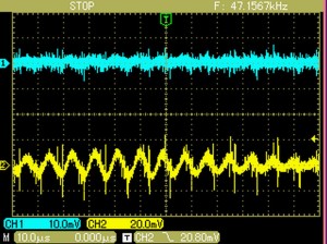
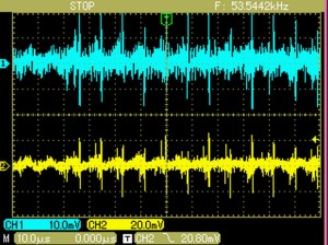
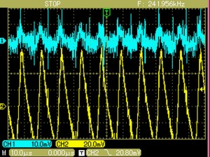
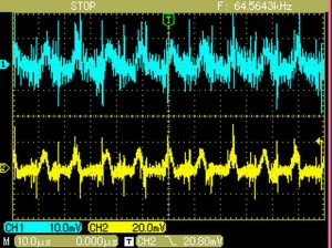
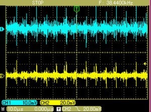
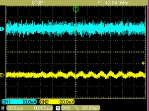
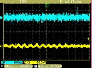
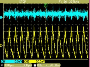
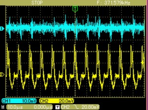
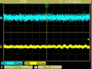
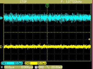
- the scope is set at 10us/div;
- the lightcyan trace indicates the voltage to be measured, and it is 10mV/div;
- the yellow trace indicates the Aref voltage, and it is 20mV/div.
Here follows the results.
Case 1
- Netduino powered by USB cable;
- Aref connected directly to the 3V3 supply;
- The LCD shows the ADC value spanning: 484-491
Case 2
- Netduino powered by USB cable;
- Aref connected to the 3V3 supply, via a 1mH inductor and a 47nF capacitor (to the ground);
- The LCD shows the ADC value spanning: 485-488
Case 3
- Netduino powered by USB cable;
- Ethernet cable plugged in;
- Aref connected directly to the 3V3 supply;
- The LCD shows the ADC value spanning: 476-494
Case 4
- Netduino powered by USB cable;
- Ethernet cable plugged in;
- Aref connected to the 3V3 supply, via a 1mH inductor and a 47nF capacitor (to the ground);
- The LCD shows the ADC value spanning: 483-491
Case 5
- Netduino powered by USB cable;
- Ethernet cable plugged in;
- Aref connected to the 3V3 supply, via a 1mH inductor and a 47nF capacitor (to the ground);
- A 100uF capacitor across the 3V3 power supply;
- The LCD shows the ADC value spanning: 486-490
Case 6
- Netduino powered by Vin (regulated power supply);
- Aref connected directly to the 3V3 supply;
- The LCD shows the ADC value spanning: 484-489
Case 7
- Netduino powered by Vin (regulated power supply);
- Aref connected to the 3V3 supply, via a 1mH inductor and a 47nF capacitor (to the ground);
- The LCD shows the ADC value spanning: 484-488
- Netduino powered by Vin (regulated power supply);
- Ethernet cable plugged in;
- Aref connected directly to the 3V3 supply;
- The LCD shows the ADC value spanning: 450-480
- NOTE: serious ripple on the supplies, even on the op-amp stage
Case 9
- Netduino powered by Vin (regulated power supply);
- Ethernet cable plugged in;
- Aref connected to the 3V3 supply, via a 1mH inductor and a 47nF capacitor (to the ground);
- The LCD shows the ADC value spanning: 453-485
Case 10
- Netduino powered by Vin (regulated power supply);
- Ethernet cable plugged in;
- Aref connected to the 3V3 supply, via a 1mH inductor and a 47nF capacitor (to the ground);
- A 100uF capacitor across the 3V3 power supply;
- The LCD shows the ADC value spanning: 489-492
Case 11
- Netduino powered by Vin (regulated power supply);
- Ethernet cable plugged in;
- Aref connected to the 3V3 supply, via a 1mH inductor and a 47nF capacitor (to the ground);
- A 220uF capacitor across the 3V3 power supply;
- The LCD shows the ADC value spanning: 489-491
Conclusions.
On the “Revision B” of Netduino there is a greek-pi LC-filter on the Aref, and this surely is a good improvement in term of noise rejection. However, it seems that the USB power coming from our PC is not so good to be used as source for measurements. In such a cases, a decent regulated power supply is recommended, along a low-inductivity capacitor (e.g. tantalum) on the 3V3 supply. Best results are achieved with a traditional power supply (i.e. NOT switch-mode).
Overall, I suggest to refine the stability of our readings with a simple yet effective low-pass algorithm.
Sempre molto interessanti i tuoi post su Netduino, per risolvere i miei problemi farò sicuramente riferimento a questi tuoi test, grazie mille 🙂